
Contents:
Introduction
The Layer Editor is the latest update to our PCB Visualizer.
Since the introduction of the PCB Visualizer we have added a number of specialized editors that allow modifying the imported customer data, for example the Outline/Milling and the Drill/Slot editor.
These editors are very useful in where data changes are necessary which cannot be easily done in the original CAD software or it is quicker to do in the PCB Visualizer.
We plan to introduce more specialised editors and realised that some basic layer editing tools would be useful.
This is why we have now introduced the first version of our Layer Editor. This is in addition to our Solder Paste Editor.
Selecting Layers to Edit
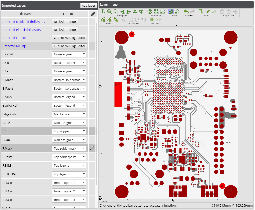
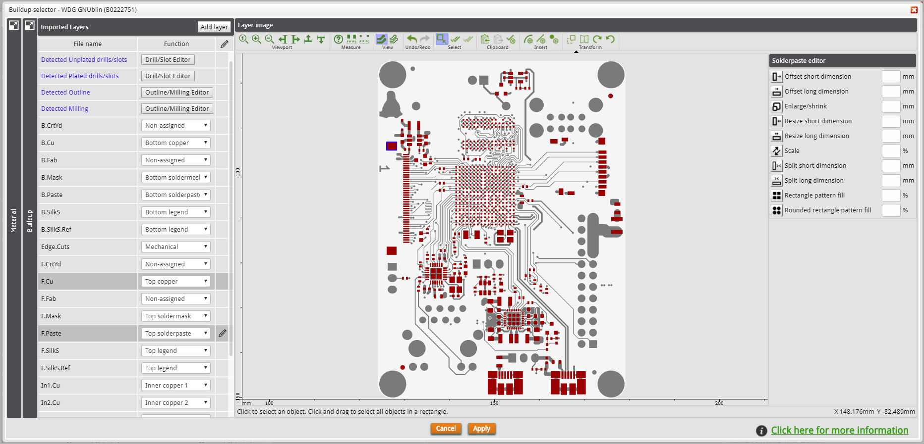
Editing layers is available from the Buildup Editor when data is uploaded and fully analysed. This editor tool is already used to identify the function of each layer of the PCB build-up.
To activate the layer for editing, click in the right column of the Imported Layers table.
If the layer was not yet selected, it will become selected and a black pencil icon will indicate that this is the layer currently in edited mode.
Click again to deactivate the edit mode.
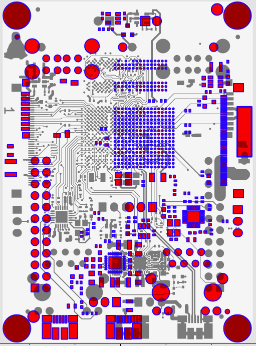
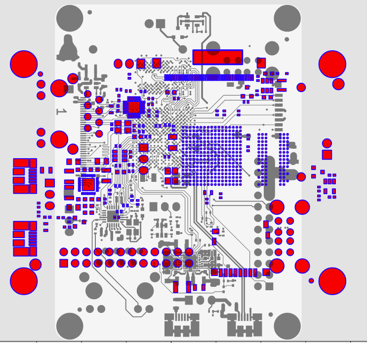
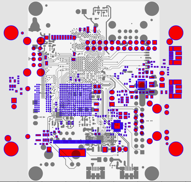
The layer in editing mode is displayed in red.
You can select more layers to be displayed by clicking in the layer in table with the CTRL key pressed. The extra layers are displayed in grey.
Objects that overlap are now displayed in dark red.
The objects of layer selected for editing that does not overlap the extra layers are shown in bright red.
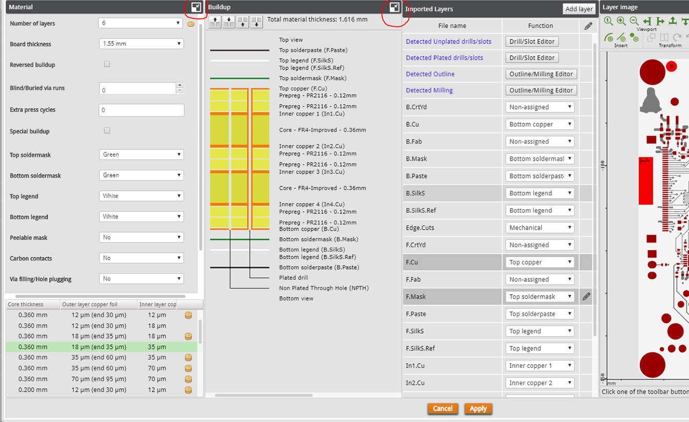
For smaller or lower resolution screens, you are able to fold away the Material and Buildup view panels to make more space for the Layer Image.

Simply click on the icon to recover the hidden panels.
Adding Layers
It may happen that a layer is missing from the imported data set, e.g. a Solder Paste layer.
Using the Add layer function you can add a layer to your data set.

Click the Add layer button to create a new layer. A popup will open where you specify the name of the layer, type the unique layer name and click OK.

The new layer will be added to the Imported Layers list.
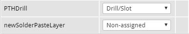
Now assign a function to the layer and use the editing functions to add data to the layer.
Viewport
The viewport toolbar is always available, whether a layer is edited or not.
![]()
![]()
The following functions are available for the displayed layers:
![]()
![]() Total view – Display all data in the board outline.
Total view – Display all data in the board outline.
![]()
![]() Zoom in – with a factor x2. The image center point is unchanged.
Zoom in – with a factor x2. The image center point is unchanged.
![]()
![]() Zoom out – with a factor x. The image center point is unchanged.
Zoom out – with a factor x. The image center point is unchanged.
![]()
![]() Pan left – Moves the viewport to the left, which moves the image to the right.
Pan left – Moves the viewport to the left, which moves the image to the right.
![]()
![]() Pan right – Moves the viewport to the right, which moves the image to the left.
Pan right – Moves the viewport to the right, which moves the image to the left.
![]()
![]() Pan up – Moves the viewport up, which moves the image down.
Pan up – Moves the viewport up, which moves the image down.
![]()
![]() Pan down – Moves the viewport down, which moves the image up.
Pan down – Moves the viewport down, which moves the image up.
These functions can also be performed by using the mouse:
- Click with the left mouse button to zoom in.
- Click with the right mouse button to zoom out.
- Press a mouse button and drag to pan.
- Use the mouse wheel to zoom in and out.
Measure
The measure toolbar is always available, whether a layer is edited or not.
![]()
![]()
The following functions are available:
![]()
![]()
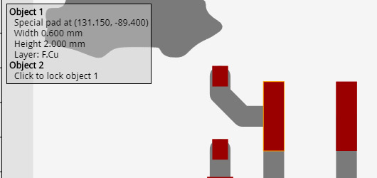
Object info – Click this button to activate the function.
If this function is active, information is displayed about the object at the mouse location in the top left corner.
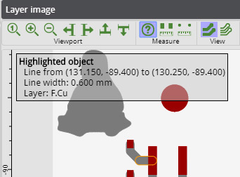
The information contains the shape and position info along with the layer on which the object is found.
The selected object is displayed with an orange outline.
If there are multiple objects available at the same location, click the right mouse button to display the information on the next object in the stack. Objects from all selected layers can be queried.
To deactivate the function press the ESC key, click the button again or select another function.
![]()
![]() Measure object clearances – Click this button to activate the function.
Measure object clearances – Click this button to activate the function.
If this function is active, you can select 2 different objects and measure the clearance between both.
Move the mouse over the first object and click to lock the first object. In case multiple objects overlap, you can click the right mouse button to highlight the next object in the stack before selecting it.
Then move the mouse over the second object. Information about both objects is displayed together with the clearance between both objects.
Click again to select another object as the reference object.

To deactivate the function press the ESC key, click the button again or select another function.
![]()
![]() Measure point distance – Click this button to activate this function.
Measure point distance – Click this button to activate this function.
If this function is active, you can select 2 different points and measure the clearance between them.
Move the mouse to the location of the first point, an orange cross cursor will snap to special points in the data set, e.g. center points of flashes or start and end points of lines.
To override the snapping functionality, hold the Shift key pressed. Click to lock the first point.

Then move the mouse to define a second point. The coordinates of both points are displayed together with the distance between both points. Using this method it is possible to measure e.g. the pitch of a component.

To deactivate the function press the ESC key, click the button again or select another function.
View
The measure toolbar is always available, whether a layer is edited or not.

These functions define how the layer data is displayed.
![]()
![]() Solid view – All data is displayed as filled areas. In this mode it is possible that small objects are not shown if they are smaller than 1 pixel.
Solid view – All data is displayed as filled areas. In this mode it is possible that small objects are not shown if they are smaller than 1 pixel.

![]()
![]() Outline view – All data is displayed as an outline (one pixel wide). In this mode all objects are always visible.
Outline view – All data is displayed as an outline (one pixel wide). In this mode all objects are always visible.

Undo/Redo
The undo/redo toolbar is always available, whether a layer is edited or not.

Click to undo button to undo the last action and Click the Redo button to redo the action that was undone.
Select
All editing functions work on the selected objects, if no objects are selected the the editing functions are disabled.
![]()
![]()
Only data from the layer with the pencil icon on the right can be edited,
The following functions are available:
Select
All editing functions work on the selected objects, if no objects are selected the the editing functions are disabled.
![]()
![]()
Only data from the layer with the pencil icon on the right can be edited,
The following functions are available:
![]()
![]()
Select/Deselect manually – Use the mouse to select data.
Move the mouse over the object and click with the left mouse button to select it.
Alternatively, press and hold the right mouse button to drag across the objects on the layer, all objects that overlap the rectangle will be selected.
Use the right mouse to deselect objects in the same way.
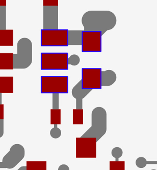
Selected objects are shown with a blue outline.
To deactivate the function press the ESC key, click the button again or select another function.
![]()
![]()
Select all – Selects all objects from the edited layer.
![]()
![]()
Deselect all – Clears the selection.
Clipboard
Use the clipboard to copy data from one layer to another.
![]()
![]()
The following functions are available:
![]()
![]()
Copy to clipboard – Clicking the button copies the selected data to the clipboard. Data copied to the clipboard remains there until the next copy action.
![]()
![]()
Paste from clipboard – Clicking the button copies the content of the clipboard to the edited layer and can be pasted multiple times. The function is only active if there is data on the clipboard .
![]()
![]()
Delete the selected data – Clicking the button deletes the selected data from the edited layer, this function is only active if there is data selected.
Insert
Use the insert function to add simple data to the edited layer.

The insert functions a currently available for circular shapes.
The following functions are available:
![]()
![]()
Insert arc – Insert a circular arc using a circle with given diameter.
Clicking the button activates the insert arc function and shows the arc parameters popup.

The standard flow is to first click on the start point of the arc, then on the end point and then define the third point of the arc. Click again on the third point to accept the arc.
Alternatively you can enter the different parameters in the popup window and click Apply to accept the arc.
Using the arrow buttons you can determine which click action is activated.
![]()
![]()
Insert line – Insert a line using a circle with given diameter.
Clicking the button activates the insert line function and shows the line parameters popup.

The standard flow is to first click on the start point of the line, then on the end point. Click again on the end point to accept the line.
Alternatively you can enter the different parameters in the popup window and click Apply to accept the line.
Using the arrow buttons you can determine which click action is activated.
![]()
![]()
Insert flash – Insert a circle flash using a circle with given diameter.
Clicking the button activates the insert flash function and shows the flash parameters popup.

The standard flow is to click on the center location of the flash. Click again on the flash point to accept the flash.
Alternatively you can enter the different parameters in the popup and click Apply to accept the flash.
Using the arrow buttons you can determine which click action is activated.
Transform
Use the transform functions to transform existing data.

All transform functions work on the selected data.
The following functions are available:
![]()
![]()
Offset – Move the selected data to a new location.
Clicking the button activates the offset function.
Move the mouse to the start location to grab the data, you will see that the cross-hair cursor snaps to the data for more accurate positioning.
Press the mouse button and drag the selected data to its new location. Release the mouse button to move the data.


![]()
![]()
Mirror – Mirror the selected data horizontally around the center of the selected data.
![]()
![]()
Rotate clockwise – Rotate the selected data 90 degrees clockwise around the center of the selected data.
![]()
![]()
Rotate counter-clockwise – Rotate the selected data 90 degrees counter-clockwise around the center of the selected data.
Version
Once you have edited your data, you might want to know the differences between the data you supplied, and the data we will be processing. Maybe you want to revert all your changes to the data you originally supplied.
![]()
![]()
The following versioning functions will assist you in this:
![]()
![]()
Compare – To compare your current data with the data you supplied in your data set, click the compare button.
The original data will be shown in grey which is not available in the edited data is displayed in grey, the edited data which overlaps with the original data is displayed in dark red and the edited data which does not overlap with the original data is displayed in bright red.
In case the edited data is identical to the original data, a message will come up to inform you.

![]()
![]()
Revert – The layer is reverted to the data you originally supplied.
In case the edited data is already identical to the original data, a message will pop-up to inform you.
Editing Solder Paste Layers
We have developed a set of specific tools which can help you to optimise your Solder Paste layers as a basis for accurate Solder Paste stencils.
CAD systems either output no specific file to define the paste pads or supply a paste definition which is an exact copy of all SMD copper pads that are free of Soldermask.
Higher technology PCB’s with fine pitch components and complex pad configurations mat require a more advanced paste data preparation.
The Solder Paste tools are made available if a solder paste layer is selected as edited layer.
The functions become active if data is selected and work on the selected data.
Most of the editing functions are separated to allow editing of the long dimension and the short dimension independently. This allows you to use the function on paste pads regardless of their rotation.
In case of square shapes, the short dimension is the width and the long dimension the height.
Offset
Type the value in mm for the offset and press Enter or click the corresponding Offset button.
Positive values will offset paste pads to the right or top. Negative values will offset the paste pads to the left or bottom.

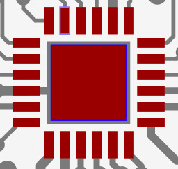
If you also selected the corresponding copper layer as extra layer, if the Solder Paste data that overlaps with the copper data will be shown in dark red otherwise, it is shown in bright red.

Enlarge/Shrink
You can enlarge or shrink any selected paste pads by an absolute dimension value. Type the value in mm and press Enter or click the Enlarge/Shrink button.
Positive values will add the given dimension to all sides of the selected pads. Negative values will reduce the size of the selected pads on all sides by the given value.
Resize
You can resize any selected paste pads by an absolute dimension value.
![]()
![]()
Type the dimension in mm and press Enter or click the corresponding Resize button.
Positive values will enlarge the size of the pad by the dimension entered and negative values will reduce the size of the pad by the dimension entered. Pads are resized from both sides, so the center of the pad remains unchanged.

Scale
If the Solder Paste opening will result in too much Solder Paste being deposited the a scaled reduction of the aperture opening is required on selected areas. In this case you can scale various sized paste pads to make them smaller by a given percentage.
Type the value for the scale and press Enter or click the Scale button.
![]()
![]()
The value is the percentage of the new surface area compared to the original surface area, so a value of 90 will reduce the pad to 90 percent of its surface area. Scaling is performed from all sides while the centre of the pad remains unchanged.
The scale value cannot result in paste pads of less than 50% of their original size.

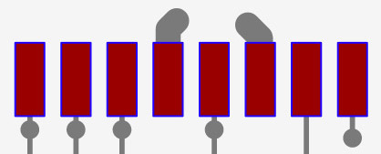
Split
Another way to reduce the Solder Paste surface area is to split the paste pad into smaller pads and can be achieved by using the split function.
This function will split the paste pad in 2 by adding a gap of the given size in the center of the original pad.
Type the value of the gap in mm and press Enter or click the corresponding Split button.

The gap value should be a positive value and cannot be more than half of the size of the original pad.

Pattern fill
In some cases you need to further optimise the paste surface. For larger surfaces it is sometimes better to fill the surface with a pattern of smaller shapes.
This can be done manually using the editing tools described above. However, we have developed an automated pattern fill function which will generate an optimised pattern according to your scale value.
This pattern fill function will split the original pad in either rectangles or rounded rectangles taking into account the minimum distance between 2 paste pads in order to still have enough remaining stencil material so the stencil remains stable as very thin parts of stencil material may bend or break during operation.
Type the value for the scale and press Enter or click the corresponding Pattern fill button.
The value is the percentage of the new surface area compared to the original surface area, a value of 90 will reduce the pad to 90 percent of its original surface area.
The algorithm will either reduce the size of the pad, or split the pad in multiple pads with a stable gap in between.
![]()
![]()
![]()
![]()

![]()
![]()

![]()
![]()
Save
To apply your changes click the Apply button, this will update the images in the PCB Visualizer.
To save the changes in your basket, click the Save changes button in the PCB Visualizer.


