

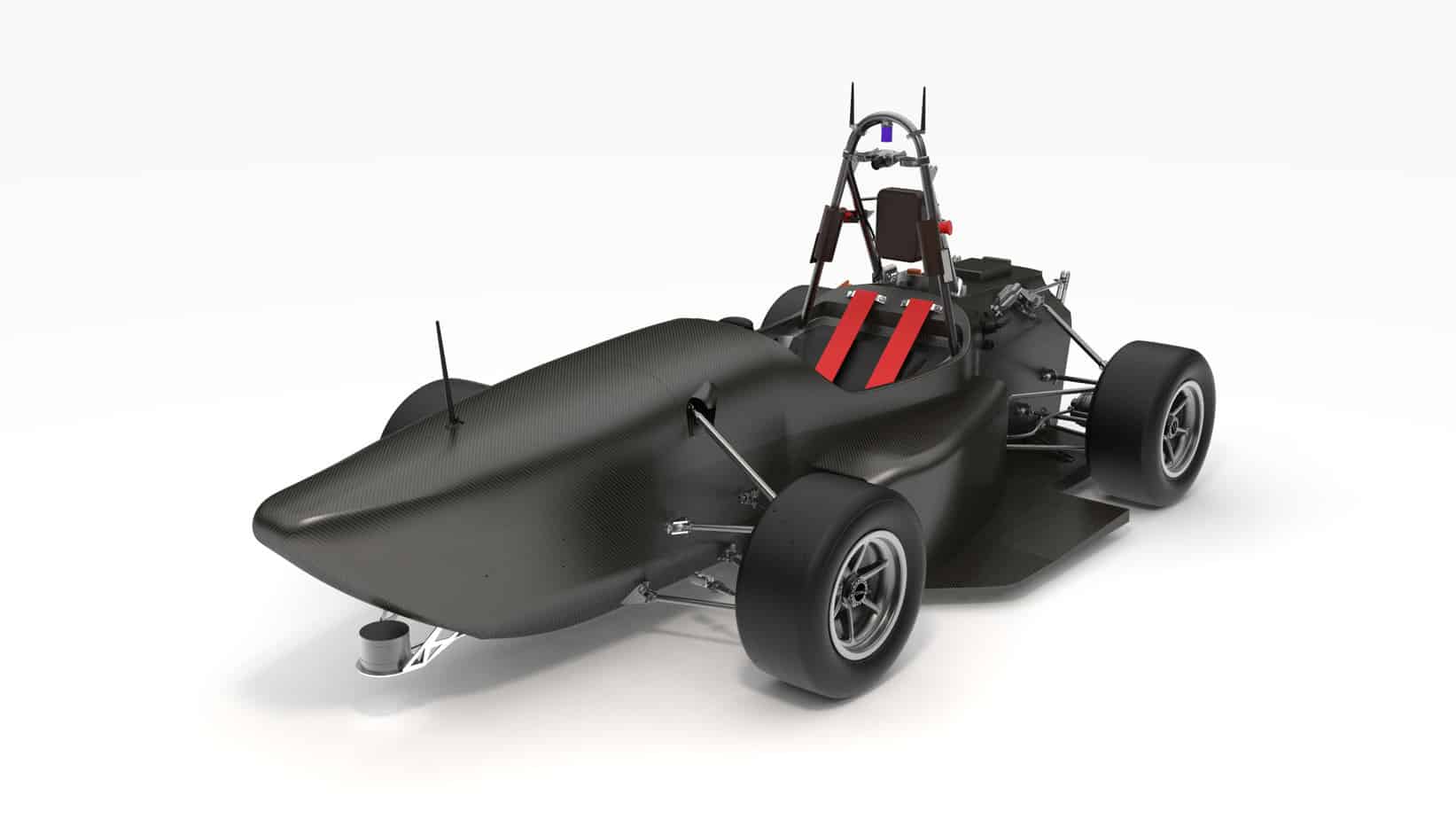
The team is reengineering the FST09e prototype, the last electric prototype developed by FST Lisboa, in order to transform it into a driverless car, the FST10d. The power supply of the FST09e consisted of an array of 2 DC-DC’s in parallel connected to the High Voltage battery outputting a fixed voltage of 24 V. This solution was able to handle up to 400 W, not enough considering the new hardware necessary for the autonomous functionality, steering actuator, powerful computer to run the autonomous pipeline, etc. The team decided to develop a 24 V battery using lithium-polymer cells and for this reason we also had to develop a Battery Management System to ensure the correct and safe functioning of the battery as well as to comply with the strict and extensive set of Formula Student rules.
Let’s take a closer look into the development of the Low Voltage Battery Management System PCB!
The Low Voltage Battery Management System’s function
The Low Voltage Battery Management System or LV BMS as we call it, has three primary functions:
- Cell monitoring, voltage and temperature;
- Power stage control, current and voltage measurement, switch battery on and off;
- Communication with exterior devices (CAN bus protocol)
After carefully choosing components to meet the above functionality, a schematic diagram for the entire system is sketched.


The Circuit Design
The circuit uses as a Micro Controlling Unit the STM32F405RGT7TR chip from STMicroelectronics. It offers plenty of IO’s, up to 15 communication interfaces such as CAN and SPI, both needed for the project and RTOS (Real Time Operating Systems) can be used to improve task scheduling, ensuring better program flow and event response.
A LTC6811-1, 12 Channel Multicell Battery Monitor from Linear Devices is used for cell temperature and voltage measurement as well as cell balancing. This device communicates via SPI with the Micro Controlling Unit (MCU) in order to provide crucial information regarding the lithium battery cells.
The battery was primarily intended for a 24 V application, having the possibility to connect up to 12 cells in series allowed the team to design a solution easily upgradable to a 48 V battery, standard in the automotive industry.
All the connections are routed carefully on the PCB and components placed, a process which takes the most amount of time and dedication!


After the layout is finished, a 3D preview of the final product can be seen:
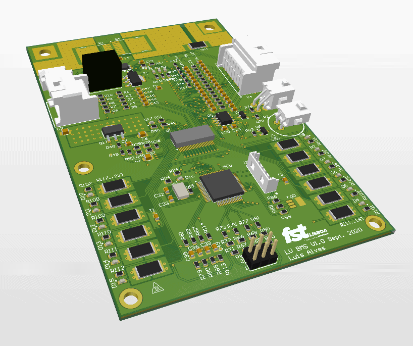
The final product meets all the specifications and beyond:
- Supports a configuration of 24 V to 48 V;
- Monitors up to 6 temperatures;
- 3 ambient temperature sensors;
- Overcurrent, Over and Under voltage protection;
- Power Stage capable of handling 100 A peak current;
- Optional Buzzer to signal battery failure or other software implemented functionality;
- Software controlled RGB LED;
- GPIO Port for future expansion;
- CAN bus interface.
We want to thank Eurocircuits for their support in our Project!
![]()
![]()
For more information about our project, please visit our website FST Lisboa
Be the first to read all about our news and information. Follow us on


