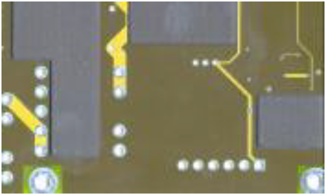
Introduction
Heatsink paste is a paste that consists of a special polymer which is filled with finely dispersed solid particles.
The dispersed solid particles provide the thermal conductivity needed for the paste to act as a heatsink.
Generating Data Output
Always clearly indicate on which side of the PCB the heatsink paste is to be applied.
This can be on one side or on both sides.
When generating output please include the board outline.
This is best done using a small line – e.g. 0.500mm (20mil) wide – where the center of the line is the exact board outline.
We will remove this line in the actual production data we use for manufacturing your boards.
IMPORTANT
If you require Heatsink Paste on your PCB please ensure this is clearly indicated.
This should be done by using correct file naming and clear buildup or layer sequence description in the Mechanical layer.
See PCB Design Guidelines – Input Data Requirements and Mechanical Layer pages.
Specifications
The area to where the paste is to be applied must be free of Soldermask.
- (A) Minimum paste on copper overlap: 0.200mm (8mil).
- (B) Minimum paste on Soldermask overlap: 0.100mm (4mil).
- (C) Minimum distance between paste and any adjacent Soldermask opening: 0.500mm (20mil).
- (D) Minimum distance between paste and the PCB outline (incl. NPTH holes and slots): 0.500mm (20mil).
- Minimum paste line width: 0.300mm (12mil).
The recommended end size of a heat via should be between 0.800mm (32mil) and 1.200mm (48mil).
The recommended coating thickness of the paste is 100µm (4mil) or 200µm (8mil).
Heatsink paste is NOT compatible with Immersion Ag or Immersion Sn as plating finish.
See also:


