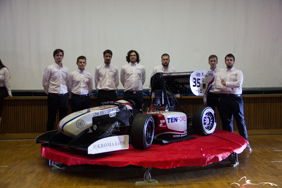
Belgrade Formula Student Team “Road Arrow” believes in their chances.
To have a fast and reliable race car means to have fast and reliable electronics. This is the reason that one of the primary goals of Formula Student Team “Road Arrow” from the University of Belgrade set at the beginning of season 2017/2018, was a complete overhaul of all electronic systems of the vehicle. This required detailed planned wiring, effectively programmed microcontrollers and reliable PCBs that would support our data acquision and processing as well as control of the vehicle. This is where Eurocircuits came in and agreed to build all of the necessary PCBs we had designed.
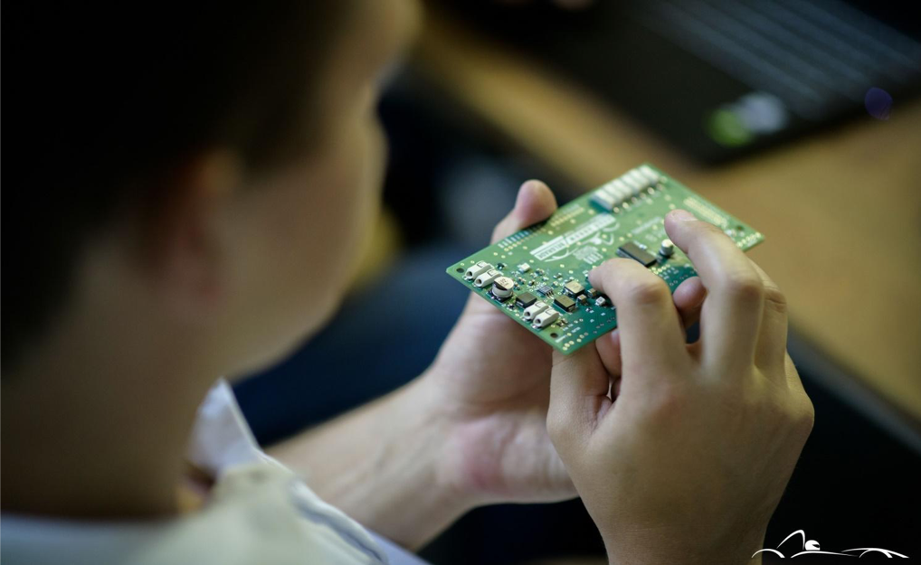
Needless to say that Road Arrow would not be the same without the help of Eurocircuits. Almost every electronic subsystem has its own PCB. These are:
- Main relay board: Until this year main relays and fuses were placed in a box with no proper space management. This year we have designed a special PCB on which all relays will be mounted. This elegant solution significantly reduced required space for relays and fuses and simplified maintenance and eventual replacement of parts. Special caution was taken in designing due to large currents that heat up the board.
- Shifter board: An important part of transmission switch system which processes the signals from the shifters in the cockpit to the gear shift mechanism in the powertrain.
- Main Unit board: Along with the Electronic Control Unit represents the brain of the vehicle. This is the reason that this board was the most complex of all to design. The board has mountings for GPS, GSM, Gyroscope, TRF and SD Card modules. A STM-F746ZI Nucleo microcontroller is used to coordinate all of the information that flows through the board, which includes reception of information from the modules, their processing, further sending to other units and storage for later analysis.
- Analogue sensor unit board: Because of system decentralization we needed two boards both with the same task: Acquisitionof analogue data from sensors, ADC conversion and further flow via CAN. This is done using a STM8a MCU.
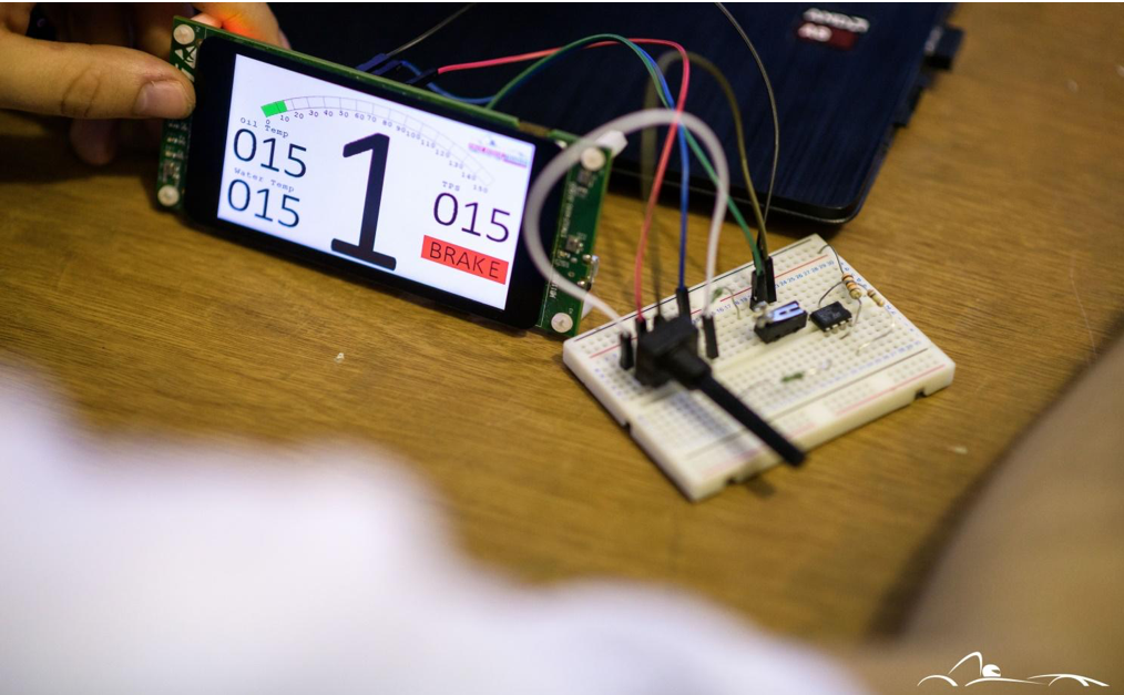
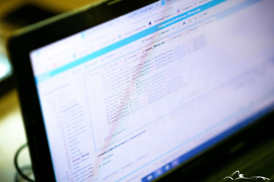
- Dashboard electronics board: This year we have devoted special attention to our drivers real time information feed about vehicle condition during race. For this reason we have installed a LCD display (STM32 F469NI-Discovery board). Critical information such as speed, rpm, temperature and pressure readings etc. are received via CAN and displayed on several slides which are manuallychangeable by a special button fitted on the steering wheel. Display graphics are programmed from scratch in a way that the driver with a single glance can obtain information about the vehicle in motion without losing focus on the driving itself. Because of the importance of RPM to the driver, it is displayed by a set of diodes in a bar style display. A PCB board is used for mounting the display and diodes as well to communicate between the display and the rest of the system.
As we said before, careful cable management is a crucial part of every serious vehicle. Since last year we have implemented an effective way of wiring the vehicle: instead of laying wire by wire in the chassis we used a method used by big automotive and aerospace companies and assembled the whole wiring system on a table and laid it at once in the chassis. This year we have even more improved our wiring harness and in advance created a wiring part in our CATIA model of the vehicle which gave us precise information of length and position of every cable in the car. We used automotive standards in all electronics subsystems. Internal communication between microcontrollers are not an exception. A standardized CAN protocol is enabling a huge data flow capacity and therefore fast information update. Standardized cable coloring and marking and automotive connectors were used as well.
The GSM module mentioned before is used to maintain live communication connection between the driver and the team at pitstop. A custom built desktop application is used to display all the information gathered from sensor units and ECU, which are mostly the same information that the display has. A TRF module is used to send the info to the computer. This enables the crew to easily coordinate with the driver and warn him about potencial faults by reading telemetry data.
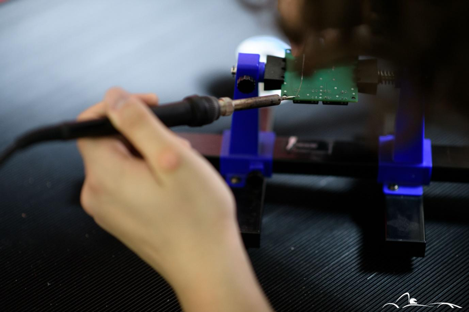
Building a reliable and sophisticated electronics system required serious tools so an effort has been made on upgrading electronics laboratory equipment in the team workshop.
PCBs designed by our members from the subteam for Electronics and built by Eurocircuits are a proof that students, most of them still on bachelor studies can undertake a complex task of building a race car with appropriate support from manufacturing companies. Even though we have successfuly tested the PCBs in the laboratory the real tests are yet to come when the car rolls up on Riccardo Palleti and Autodromo Most racing circuits this summer. We look forward to continue our work with Eurocircuits, especially due to the fact the team plans on switching its production from combustion engine to an Electro powered vehicle for the seasons ahead, were PCB designing skills are much more demanding.

