Delft – Project MARCH IV

Project MARCH IV
The essential electronics in the MARCH IV exoskeleton
When you are interested in robotic devices, then the electronics in exoskeletons should not be overlooked.
Project MARCH is a student team from the Delft University of Technology that designs, builds and tests a new prototype of exoskeleton every year.
The use of this exoskeleton is meant for paraplegics: people with a spinal cord injury who have lost all functionalities of the legs and the corresponding senses.
The exoskeleton gives the user the ability to stand up and walk again.
At this moment in time there already exist three prototype MARCH exoskeletons.
And this academic year the team has been working on the latest version, the MARCH IV.
Before we can dive into the electronics used in the MARCH IV exoskeleton, you need to have a global view of how the exoskeleton functions.
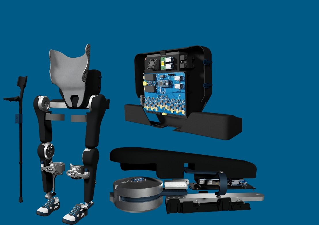
The exoskeleton consists of 4 different sets of joints.
Two sets of hip joints on both sides, one set of knee joint on both sides and one set of ankle joint on both sides.
With the use of these hip and knee joints, the exoskeleton is able to take steps forward and to the side.
The ankle joint makes it easier to climb up a slope without hurting the feet of the user.
These joints are controlled by the so-called input device, which is located in the crutch and consists of a screen with buttons.
With this input device the user can command which action to perform.
These actions are for example walking forward, sitting down or ascending a stair.
The team consists of 23 enthusiastic students, where three students are responsible for the electronics in the MARCH IV exoskeleton.
They are responsible for several electronic systems; the main power supply, distribution of power, the peripherals and the data communication.
The Power Supply
The power supply in the MARCH IV consists of a battery.
For monitoring the battery and protecting it, a battery management system is used.
Aside from being save to use, there are other requirements imposed on the battery that need to be taken into account.
The battery needs to be as small as possible and still have enough power available for a minimum run time during the competition.
It also needs to supply the right amount of voltage to properly drive the motors.
The power resulting from the battery needs to be distributed in a controlled and safe manner and its flow needs to be monitored.
The power is distributed to different parts of the exoskeleton, such as the peripherals.
These are for example the buttons, sensors and other components, as a vibrating unit in the input device.
To send information between the different parts of the exoskeleton, including the peripherals, the motor controllers and the main computer, clear communication is essential.
The communication protocol used in the MARCH IV is called EtherCAT.
For the interface between the sensors and EtherCAT, custom made embedded software is used.
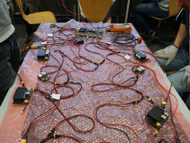
All these devices in the MARCH IV need to be connected to each other with cables for both power and communication.
So, where does Eurocircuits come in and deliver their contribution?
Self-designed Printed Circuit Boards are used in the MARCH IV for the servo driver, the data communication and for the power distribution.
After we have designed our PCBs, they are manufactured by Eurocircuits.
Eurocircuits manufactures four different kind of PCBs for us. Each must fulfill different tasks and are important in their own way.
The Power Distribution Board
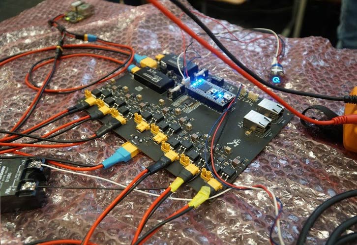
The function of this self-designed PCB is to distribute power.
It connects the battery to the motors and ensures that the other electronics in the exoskeleton are supplied with energy.
On the bottom of the PCB, shown in figure 3, there is a little circuit for every single motor connection.
With this circuit we are able to monitor its flow and to turn the motor connection on and off.
On the right top, components are placed needed for the communication with the main computer.
On the left top, you can see components responsible for converting the battery voltage (52 V) to a lower voltage (12 V) in order to power the rest of the parts in the exoskeleton, such as the sensors.
The main focus of this year was to make the PCB smaller than the year before, even though two extra motors are added to the exoskeleton.
This results into more components to placed on the PCB.
And by creating a two-sided PCB, implying a PCB with components on both sides, we did it!
The General EtherCAT Slave
The General EtherCAT Slave, shown in figure 4, collects data from the sensors and passes the data along via Ethernet ports.
There are five of those PCBs located on the MARCH IV exoskeleton.
Two on the lower legs, two on the upper legs and one in the backpack.
These are connected to the temperature sensors in the joints.
So, what components does this PCB need to function?
The micro-controller, a small pre-programmed computer, receives signals from the temperature sensor.
These temperature sensors are located in the joints and in the backpack. They are meant to detect overheating of the motors.
The microcontroller processes these signals from the temperature sensors into signals that need to be passed on via EtherCAT to the main computer.
These processed signals are send from the microcontroller to the EtherCAT Slave Controller, and this component will send this to the Ethernet ports.
The General EtherCAT Slave PCB is not our own design.
Last year the team found a great design for a small PCB created by Danny Bokma. This PCB is called the DieBieSlave.
The Servo Driver PCB
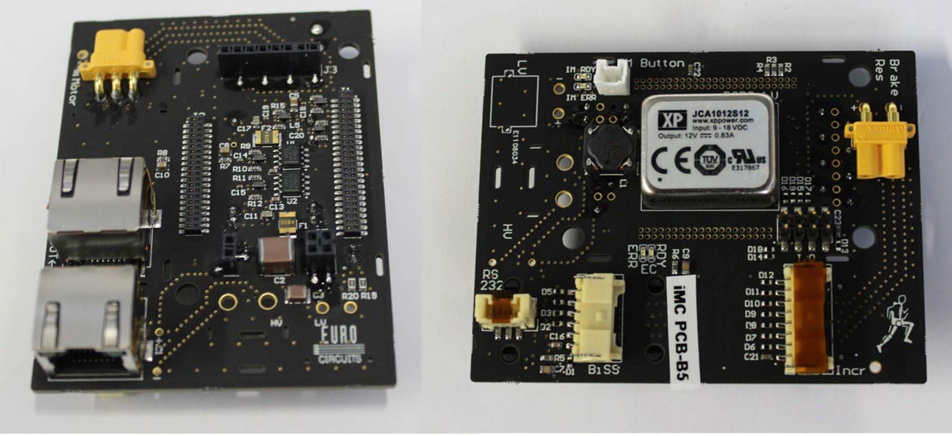
The Servo Driver PCB, shown in figure 5, is a custom breakout board concerning power and data of the motor controller.
Speaking of power.
There is a high voltage part that is meant for delivering the power towards the motors and a low voltage part that is meant for the operation of the servo driver.
Our servo driver is a component that is placed on the PCB.
The function of this servo driver is to actuate our motors correctly.
By sending the right currents at a specific time and frequency the servo driver controls the movements of the motor.
Speaking of data, there are connectors placed on the PCB that receive signals from the encoders in the joints.
These encoders are sensors that measure the angle made by the joint, or the position of the motor.
From the connectors, the signals are transferred to the servo driver and the Ethernet ports.
Via EtherCAT these signals will be send to the main computer and used in the control system of the exoskeleton.
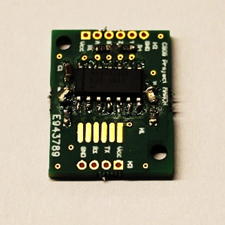
Differential Converter PCB
Noise generated by the motors in the exoskeleton can disrupt certain viable signals.
This includes viable signals that are needed for the control system of the exoskeleton.
The Differential Converter PCB is a self-designed PCB, shown in figure 6, with a differential converter on it.
With the use of this chip, noise can be minimised as much as possible and is therefore essential for carefully reading out the signals from important sensors.
Thanks to Eurocircuits
With the support of Eurocircuits we are able to let user of the MARCH IV exoskeleton stand up and walk again and therefore we are very grateful to them!
Willemijn Berkhout | Partnerships & Public Relations
T +31 (0)15 278 98 37 | M +31 (0)6 13 88 56 43
Stevinweg 1 | 2628 CN Delft | The Netherlands
willemijn@projectmarch.nl | www.projectmarch.nl

