Hand-soldering – point by point or mini-wave technique
Hand-soldering with the same high quality result as reflow or wave soldering?
Are you ready for the challenge ? Let us look at the mini-wave soldering technique.

This picture shows that tools and skills are the basics to achieve a good result in hand-soldering. You agree ?
Hand-soldering is in most cases the last step in the prototype assembly process. Why is it less controlled and more difficult than other steps in the manufacturing. It is something we all know how to do. It”s just heating up a PCB and a component to make a solder joint. Isn”t that simple?
PCB designers, technicians, electronics engineers, we all learned at school how to solder with an iron. It can be 5 or 35 years ago, but we assume that not a lot has changed. A lot did change!
Do we still take our car to a service where they have only mechanical hand-tools to fix it ? They do have a lot of tools these days to do a good repair job
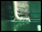
Soldering connections – Solder joint
A good solder joint is an electrical and mechanical connection which in the best condition is made in one shot with a temperature as low as possible, and as quick as possible. This rule is still valid, even when solder-alloys have changed from Sn63/Pb37 to the leadfree SAC305, SN100,.. or whatever the alloy used.
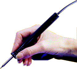
A good iron and the right skills makes the perfect start. What is the temperature of your iron today? How is the geometry and condition of your tip? What solder-materials do you use? Are you soldering lead free assemblies?
Today we show you a technique to solder a SOIC-16 (Small outline Integrated Circuit 16 I/O) or PQFP-100 with Gull Wing leads. The quality we like to match is the same or even better than in a full automated production line. We all know how to solder this point by point, but do we master the Mini-wave technique?
See more details from the SOIC in the package outline


What do we need :
- Soldering station (iron)
- Soldertip
- Solderwire
- Flux past / Flux pen
- Tweezer
- Cleaning product
- EPA zone ( ESD protected area)
How do we proceed:
- Set the temperature as low as possible considering the pcb design ( layers, copper mass )
- Insert the tip into the soldering iron
- Heat-up the tip and check the tip conditions: the solder should flow (spread evenly) over the plated tip area
- If this is not the case, clean the tip surface ( to remove oxidation)
- if this does not help, replace the tip with a new one
- Place the SOIC 16 on the PCB and attach 2 or 4 corners to hold the component in place ( Apply flux to the pads before placing the SOIC on the board)
- Add flux paste or flux to all leads/pads on the SOIC16
- Clean the solder-tip on a wet sponge or brass tip cleaner
- Add solder to the tip-end (mini-wave or conical tip)
- Point by point soldering:
- Solder all leads individually – point by point by adding the right amount of solder. The solder is provided by hand using a fine solderwire.
- Mini-wave soldering:
- Place the mini-wave tip ( parallel to the pads) on the first pin of the PQFP/SOIC and move along the pins at a constant speed. Solder all leads in less then 5-10 seconds.
- Do the same thing again on the other sides of the PQFP/SOIC
- Point by point soldering:
- Clean all Flux-residues with a cleaning solvent and ESD-safe trigger grip
- Check all solderjoints/connections with a microscope/videomicroscope/magnifier.