Oscar Romero College – Rubiks Cube Solving Robot

Introduction
We are students at the Oscar Romero College. We study Electronics-ICT in our final year. In this year, we are required to make a project which we’ll be marked on.
We were allowed to choose our own projects, provided that they were difficult enough. Several of our projects required PCB’s, which we weren’t able to produce ourselves.
That is why we contacted Eurocircuits, and this is also why they played an important role in the making of our projects. For that, we would like to thank them.
In this blog, we will explain the basic function of the PCB’s used in our projects.
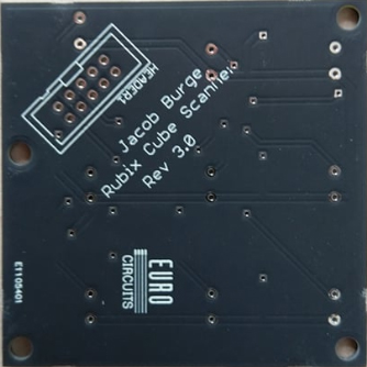
Rubik’s Cube Solving Robot
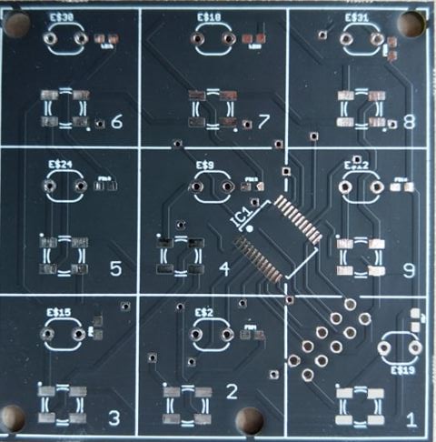
The robot itself consists out of several parts (Stepper motors, assembly and colour scanner).
The most important part is the colour scanner, it is used to scan the surface of the Rubik’s Cube and send these values to the computer.
On the PCB there are 9 WS2812b addressable RGB LED’s, 9 LDR’s with complementary resistors and a multiplexer.
The way it works is pretty simple. The LED’s emit red, green or blue light after which the returned light is measured by the LDR’s. The 9 LDR’s are each connected to the multiplexer’s inputs.
This multiplexer is controlled by an Arduino. The output of the multiplexer is connected to one of the analogue pins of the Arduino, which will measure the voltage returned by the LDR’s.
The Arduino now sends the measured values to a program. This program will solve the Rubik’s Cube and send commands to the arduino to control the stepper motors that will actually move the Rubik’s Cube.
Internet Controlled Nixie Clock
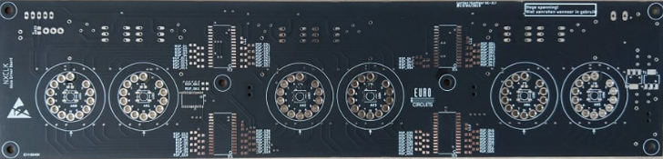
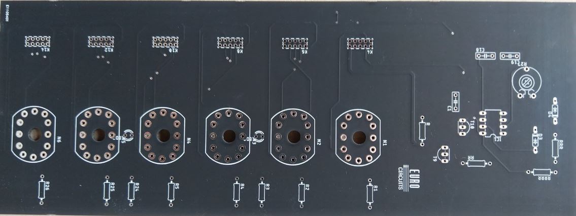
This is one of three PCB’s I require for this project. It is the most important PCB because it drives my nixie tubes. it does so in a relatively simple way.
On the PCB there are 60 MOSFETs, one for each of the cathodes of the nixie tubes.
The MOSFETs have complementary pull-down resistors and inrush current-limiting resistors.
The MOSFETs are driven by 4 16-bit I/O expanders that are controlled via the I2C-bus.
Also present on the board are 6 opto-couplers, these are used to dim the nixie tubes. The optocouplers are connected to the 180V-rail and to the anode-resistors of the nixie tubes.
There is a PWM IC on the board that drives the optocouplers and also drives 4 MOSFETs that are used to control little nixie tubes that are used as colon-separators. This IC is also controlled via the I2C-bus.
Finally, there are 6 WS1812b addressable RGB-LED’s on the board. These are used to provide a subtle underglow under the nixie tubes. They are controlled via a 1-wire interface.
All the interfaces (SDA, SCL, 1W, 5V, GND) are connected to a 5 pin-header. The 180V-rail and GND are connected to a 2-pole screw terminal.
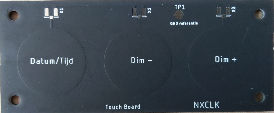
I also had another PCB produced. This PCB has 3 copper pads and some u.FL connector pads. It will be used as an input board to connect to capacitive touch circuits.
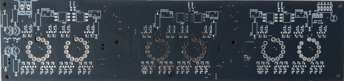
GPS-driven Nixie Clock
The Nixie tubes work on 180V and this will be supplied through the first tube on the right.
It will also supply 5V to the NE555 chip that i’ll be using to dim the nixie tubes.
The two diodes and the 1M ohm potentiometer will allow the duty cycle to vary between 5% and 95%. The transistor T9 will be connected to the 180V and the anode resistors for the nixie tubes.
The NE555 chip will be driving transistor T10 that will simply cut off the voltage from transistor T9.
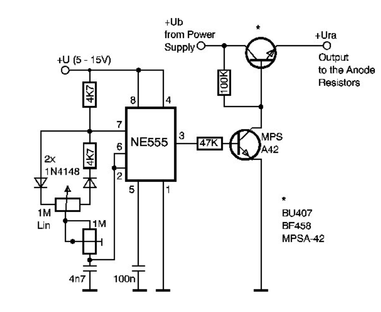
http://www.mcamafia.de/nixie/ncp_dt/nix_dim.htm
This is a schematic of the dimming circuit I based my design on. The upper transistor is T10 and the one in front of the NE555 chip I called T9.
8x8x8 LED Cube

For every color in the RGB LED’s I have 1 IC. The 3 ’74HC595 shift register IC’s are connected with 4 pins (Data-, Latch-, Blank- and the Clock pin) with the arduino MEGA.
The arduino MEGA sends Data to the parralel data outputs (Q0-Q7) of the IC’s.
The output of the shift registers drive the transistors that drive the RGB LED’s.
The capacitors that are placed next to the IC’s will make sure that ripple currents are short circuited to ground so they won’t cause interference.
Special thanks to Eurocircuits
We would like to thank Eurocircuits for the production of our PCB’s.
Their high quality PCB’s and fast production time proved really valuable for us.
They always helped us out if we had questions, which made everything much easier.