RoboTeam Twente – 2018/19 Update

The RoboTeam Twente
RoboTeam Twente is a student team from the University of Twente that has been competing over the last three years in the RoboCup Small Size League. The RoboCup is a yearly event where teams from all over the world compete with each other in different leagues.
Its goal is to advance the state of the art of intelligent robots. The Small Size League is focused on small autonomous robots playing as a team in a game of soccer. More than 20 teams from all over the world compete in this league.
During the last three years, we have designed and built every part of our soccer robot ourselves, and we are continuing to improve and innovate in all areas regarding the robot. Eurocircuits has been a partner ever since the start of RoboTeam Twente.
The biggest challenge for us as a team is to manage a yearly development cycle where many features are added or changed. This means that every year there is a complete development cycle from design to production.
This is not only true for the mechatronics of the robots, but also the other departments that depend on this. These departments are mainly the Control team and the Artificial Intelligence team.
Thanks to Eurocircuits
This means that a prototype has to be ready before the other teams can start testing their work in real life.
Here, Eurocircuits plays a big factor in our short development phase as we can order multiple iterations of prototype boards that arrive within a week. This allows us to start testing quickly.
Using Eurocircuits Visualiser as a final sanity check has saved us valuable time, in case there was something wrong in the layout of the boards. This helped us make our deadline for the design.
Also during the production phase we relied on Eurocircuits’ fast manufacturing, allowing us to have our custom and compact robots ready for the tournament.
The Robot
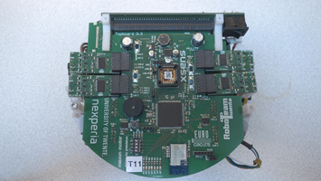
There are four significant PCBs for our robot:
- The Topboard with the microcontroller which controls all other boards. It also has most of the sensors.
- Motor drivers that control the wheels of the robot.
- The Basestation that communicates with the main computer and sends messages to all of the robots.
- The Kickerboard which controls our dribbling device and charges a capacitor to power a solenoid used for kicking and chipping the ball.
These boards each have their own difficulties but also share some common problems, namely different layout requirements and small surface area.
The layout requirement comes down to two parts;
The first part is a high power circuit for all motors and actuators.
The second part are fast signal lines, both analogue and digital.
Both types of circuitry have certain needs: thermal capabilities and noise, etc.
Balancing these has proven to be difficult.
However, being able to rely on certain factors which Eurocircuits can guarantee allows us to alleviate some of these constraints and reduce the amount of factors to consider.
Another problem has to do with the size of our robots.
The rules state a maximum size for the robot, but in order to be competitive we have to provide a lot of features for the robot.
This means that we have to be able to provide a lot of functionality in a small area. This mostly shows in weird shapes of our PCBs and density of the components and traces.
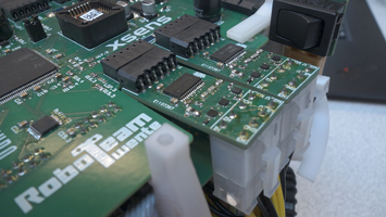
These common problems have been most present on the Topboard which houses the main micro controller, sensors and circuitry for our motor drivers.
Here, the noise has to be low on the power lines for all the sensors and micro controller, as well as being able to provide the currents that are needed for the motor drivers.
 |
 |
 |
The KickerBoard
The Kickerboard has a high frequency flyback converter which has to charge a large capacitor to 350V.
This means a high chance of noise being generated, close to the micro controller itself which is on the Topboard above.
Here the trace length and width have been crucial to minimise the noise coming from the flyback converter.
For kicking, the capacitor is discharged through a solenoid, causing a metal core to shoot out. The discharging causes a large current of 80A to flow through the solenoid for a short duration, and can as a result cause a high voltage spike on some of the data lines and even power lines.
This spike is also present on the other boards which are all close by.
Here special attention has been paid on the close decoupling of components and reduction of the surface area of the line pairs. In sensitive cases, other measures have been made to relieve them of the additional stress.
 |
 |
Motor Drivers
The main problem of the motor drivers is the large power requirement on a small surface area, while also having many different signals that need to be routed.
Here it was key to have small components which can cope with the noise and the power requirements.
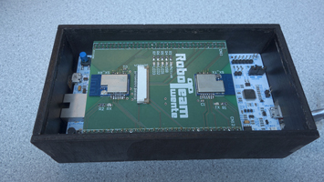
Base Station
The base station is a simple extension to a prototype board and provides debug LED’s and the main communication modules needed for communicating with our robots.
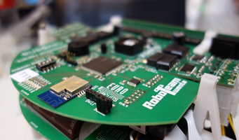
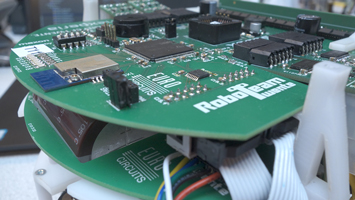
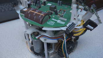
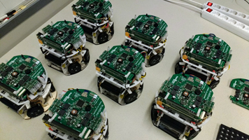
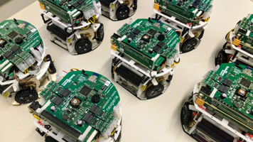
Various Images
 |
 |
 |
 |
![]()
Luuk Klein Nagelvoort
Communications manager | Software developer
Roboteam Twente | University of Twente