Swissloop in 2022

Swissloop at the European Hyperloop Week
Swissloop is a student team of ETH Zurich developing a proof of concept “Hyperloop Pod”. It’s all about high-speed travel for us, with the long-term theoretical goal of being able to reach high velocities of up to 1,000 km/h. The idea was initially sketched in 2013 and a yearly student competition was kicked-off by SpaceX in 2016. In 2021, Swissloop and other student teams took the initiative and co-founded the European Hyperloop Week, a competition focused mainly on technology innovation and long-term scalability of concepts. This summer, the second European Hyperloop Competition took place in Delft, Netherlands. Once again, Swissloop managed to secure awards for implementing innovative concepts. Especially the new propulsion system with its motor design, power electronics and control architecture made an impression with other teams, guest researchers and institutional representatives.
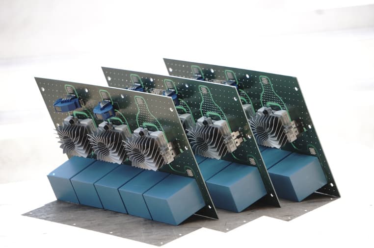
Propulsion
In the past season 21/22, the focus was put on a novel linear motor, intended to be more scalable and efficient. The motor is based on switched reluctance, which has not been widely used in linear motors so far.
Developing a new motor involves various specific design requirements for the electronics of the whole system, in particular the power electronics. In order to move the pod, the current in the motor coils has to be precisely controlled. Because of this, we have opted to go for a custom design on most PCBs, amounting to almost 10 custom boards. This allowed to realize three main aspects:
- Being able to control the motor by combining various sensor inputs.
- Being able to precisely control the current in the motor with an inverter to reproduce a target current as close as possible.
- Being able to safely operate a powerful battery with a high voltage capability to drive the motor.
With the support of Eurocircuits, we were able to have an immense amount of design freedom in our latest motor. We are very thankful for this and are looking forward to bringing the whole system together!
The motor (inverter) control has been simplified and redesigned to feature one microcontroller and FPGA pair instead of three. This also allowed to avoid having to synchronize the different chips, which has caused issues in past years.
As the FPGA (see below) is in a small BGA package, we resorted to using a 6-layer class 8E PCB to ensure all tolerances were met and we were able to fan out and escape most pins. Despite being on the limit of most tolerances, the end-product was surprisingly exact. This small board is stacked onto a larger 4-layer board which has almost 20 signal connectors going to the inverters and sensors. From this perspective, it is quite a centralised design.

For this board the PCB Visualizer® was really helpful in being able to determine if the design was really manufacturable. For the interested: 256-pin caBGA, 0.8mm pitch, 0.1mm hole size.
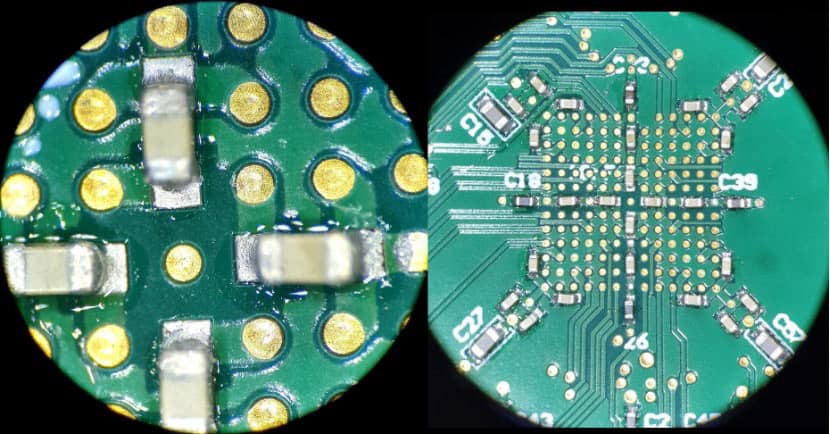
The microscope shows great tolerances on the 0.1mm filled vias for the class 8E PCB with 0402 capacitors tightly packed in between the gaps.
Attached below are some pictures of the team and tech:

Vehicle Control Unit

The Inverter Driver Board: Used for signal processing, current readings and isolation of control and high voltage boards.

Engineers collecting best traction (best propulsion) award.

The Low voltage Box: Inverter Control Unit (FPGA-based), Vehicle Control Unit, Low Voltage Power Supply.

Testing of ADCs on Inverter Driver Board.
![]()
For more information please visit the Swissloop website.
Be the first to read all about our news and information. Follow us on