Manufacturing IOT Devices

So many of the devices we use daily are connected via the internet (IoT) making our daily activities easier and with this comes the need for faster and faster connections (USB3, 5G, etc..).
It has become the norm to connect to the internet whether it is to control your central heating, manage your security or monitor your utility usage etc…
A traditional transmission line is made of a track with a reference plane for a ground return. In most cases the tracks and planes will either have air or a material (FR-4, RO4350, IS400, etc.) between them with a certain dielectric constant, εr. Finally, a matching termination circuit ― usually resistors and capacitors, need to be included in the circuit to prevent reflections as much as possible.
This has been an extremely short intro to the very complex and extensive topic on high-frequency digital and RF design. Let’s now move on to the manufacturing part of it.
For a successful high frequency design we need both the circuit to be designed well and for the PCB to be manufactured specifically with the properties we require. The role of the designer is to:
- Define the correct geometry ― buildup, distances, and widths ― and the materials ― with their respective dielectric constants ― to create the desired characteristic impedance.
- Minimise ‘interruptions’ in the transmission lines that are normally caused by vias and connectors.
- Include an appropriate terminating circuitry that reduces reflections, if needed, or plan for some form of fine-tuning after the board is manufactured.
The issue for most designers is to make such devices cost effective as the signal speeds are ever increasing making the cost difficult to control. So what better way than to use standard PCB builds with standard FR-4 material.
The only issue is that these devices require well-defined impedance lines for the signals which are outside of the spectrum of FR-4.
Now comes the manufacturer’s part: they must manufacture the correct buildup and maintain its geometry so that the resulting transmission-line’s characteristic impedance is within a certain percentage deviation from nominal (10% is an industry standard). This is what we call defined impedance.
As a designer you need to be able to rely on a PCB manufacturer that can provide a cost-effective and quick turnaround service. There must be a solution for this…
To solve these issues, we started by talking to professors and developers to understand the issues. From this we defined a standard FR-4 buildup which we believed could overcome many of these issues. After much development and testing we produced 4, 6 and 8-layer PCBs where the measured impedance was stable and consistent on well-defined test tracks.
From this we launched our DEFINED IMPEDANCE pool service.
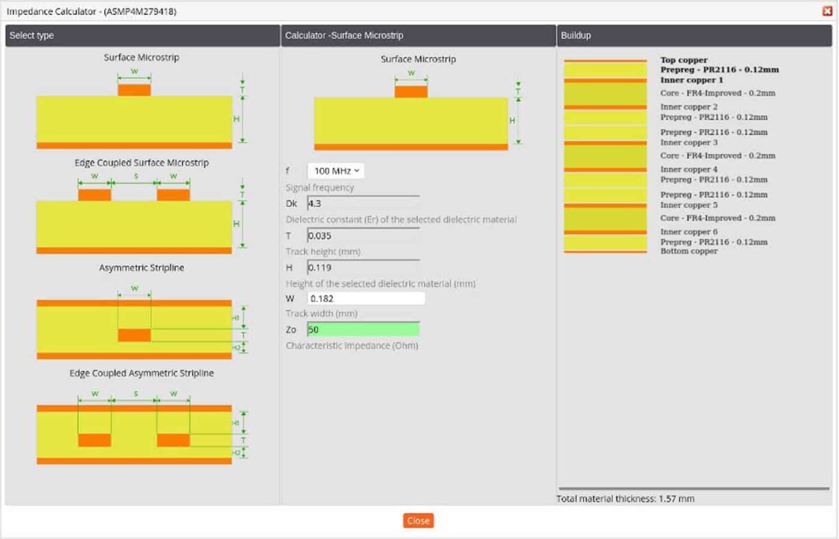
Use the standard poolable buildups in our DEFINED IMPEDANCE pool service together with our built-in Impedance calculator to define your PCB design parameters before you start your PCB layout.
About Eurocircuits
When you need a reliable and affordable single-source European electronics manufacturing partner, with over 30 years of experience, then Eurocircuits is an excellent choice. By working with us you get many pooling options, instant pricing, free DRC and DFM tools, multilingual support, and much more.
Eurocircuits offers fast and reliable on-time services without compromising on quality, using a broad range of technologies to bring you a cost-effective manufacturing service. We help you achieve Right First Time for Manufacture through virtual manufacturing so that you can get your projects to the market on-time and on budget. Let’s make your project a reality!
Bring your product to market on time and within budget – join the Eurocircuits Community


![]()

