A Partnership Between TH Aschaffenburg and Eurocircuits
Revision of the Output Filter of a High-End Audio-Digital-Analogue Converter
In the digital age, it has become standard to play your music from a compact disc (CD) or from your computer. With both devices, you can enjoy the music directly via analogue outputs. If you want to output the music signal digitally and then process it with a high-quality digital-to-analogue converter (DAC), you need a digital S/PDIF output (Sony Philips Digital Interface) on the CD player or a USB port on the computer. Some computer mainboards even have an S/PDIF output. The digital audio signal of a CD has a typical resolution of 16 bits with a sampling rate of 44.1 kHz. Computers, on the other hand, output the signal at 48 kHz.
A lot of work is done on digital audio circuits in the Digital Technology Laboratory at the TH Aschaffenburg University of Applied Sciences. In the past, a high-end audio DAC was developed as part of a bachelor’s thesis. In the analogue output circuit, ceramic capacitors in the SMD design 0805 were used in the low-pass filter. Figure 1 shows the measured spectrum for the realised audio DAC with a test signal with a frequency of 1 kHz. The measurement was carried out with an Audio Precision APX 515 audio analyser. You can clearly see harmonics at odd multiples (3 kHz, 5 kHz, 7 kHz etc.) of the test signal.
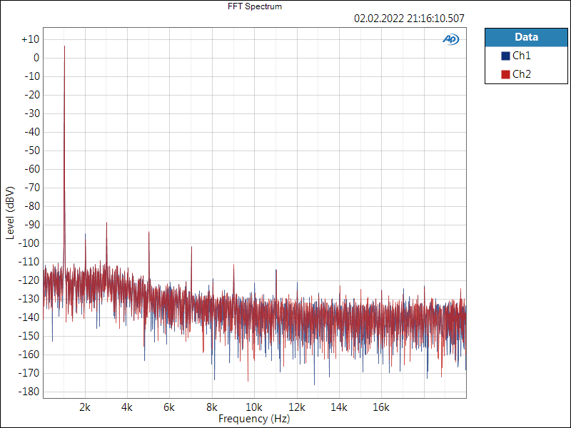
Picture 1: Measured spectrum of the audio DAC. Ceramic capacitors were used in the low-pass filter.
In another study, the low-pass filter was to be revised and the ceramic capacitors were to be replaced by film/foil capacitors of the type FKP 2 from the company Wima. These should have better audio properties than ceramic capacitors. The aim is to improve the audio quality. Figure 2 shows the revised layout, which was realised with Autodesk EAGLE. On the right side (top and bottom) the analogue output stages with low-pass filters for the right and left channel can be seen. Only the above-mentioned FKP 2 capacitors are used.
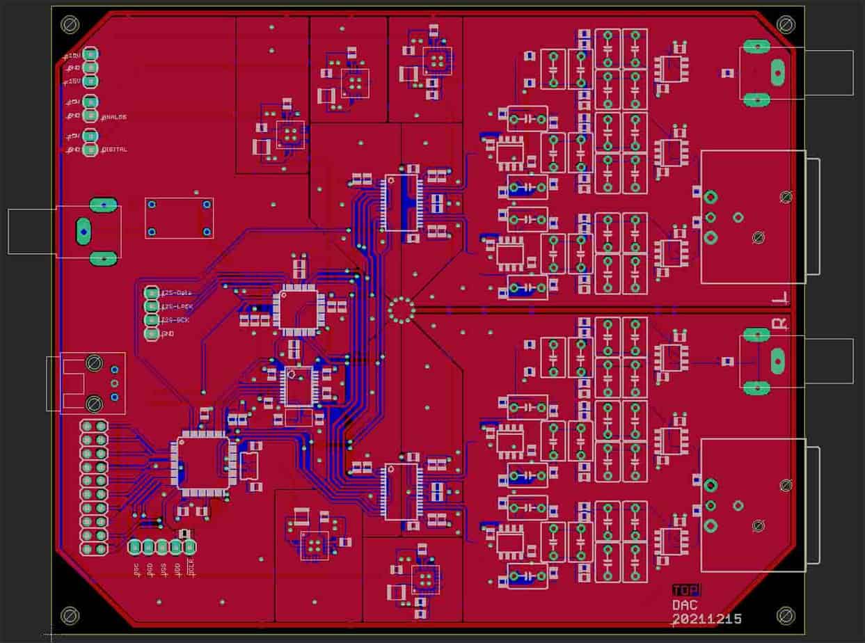
Picture 2: Revised layout of the audio DAC with FKP 2 capacitors in the low-pass filter.
The circuit board manufactured by Eurocircuits can be seen in picture 3. Furthermore, this has been racked with solder paste and already assembled with all SMD components. The next step is to solder the assembly in the reflow oven.
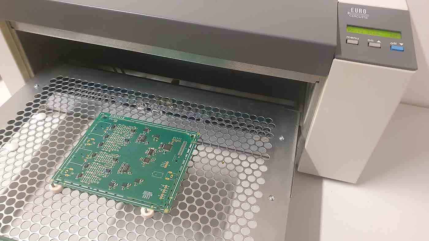
Picture 3: Prepare SMD assembled PCB for soldering in reflow oven.
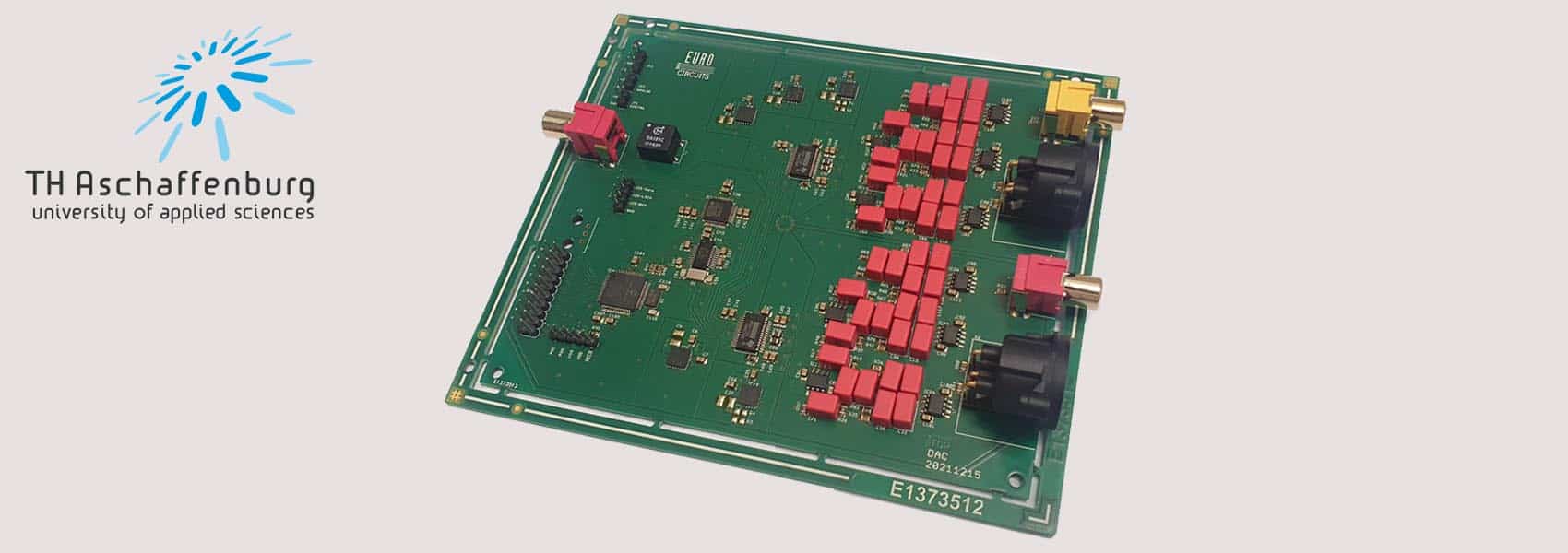
The fully assembled circuit board can be seen in Fig. 4. You can see the many red components, which are the Wima FKP 2 capacitors.
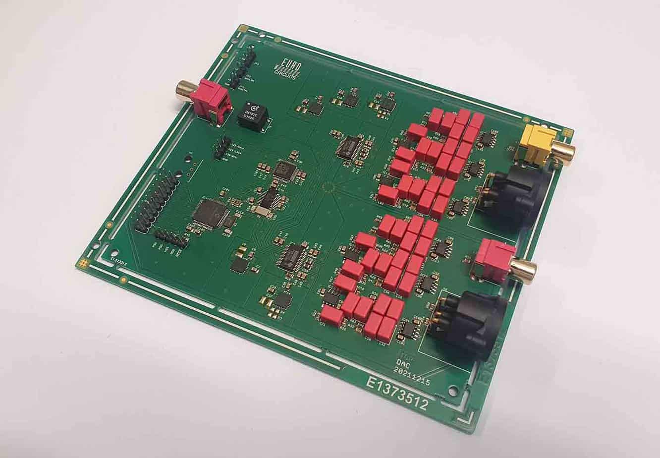
Picture 4: Fully assembled circuit board of the audio DAC with FKP 2 capacitors.
The subsequent comparison measurement shows that the harmonics at odd multiples (3 kHz, 5 kHz, 7 kHz etc.) of the test signal have almost completely disappeared. Other harmonics are clearly lower (see picture 5).
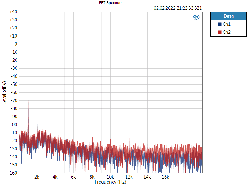
Picture 5: Measured spectrum of the audio DAC. Film/foil ceramic capacitors of the type FKP 2 from Wima were used in the low-pass filter.
Conclusion
The revised output circuit with film/foil ceramic capacitors of the type FKP 2 from Wima causes significantly fewer harmonics in the frequency range up to 20 kHz than with ceramic capacitors. All other harmonics are almost lost in the noise carpet. Thus, the aim should be not to use ceramic capacitors in analogue audio output circuits.
![]()
For more information, please visit our website.
Text by:
Student Daniel Ullrich
Under the supervision of:
Prof. Dr. Francesco P. Volpe
Labor für Digitaltechnik
TH Aschaffenburg
Würzburger Straße 45
63743 Aschaffenburg
Be the first to read all about our news and information. Follow us on