Formula Electric Belgium
At Formula Electric Belgium, we continuously strive to innovate every aspect of our race car. This year we tried to take our ECU design to the next level! The Electronic Control Unit (ECU) is the brains of the car. All information available in the car is accumulated here and processed, which in turn controls every actuator, from the cooling fans to our semi-active suspension and even the 4 in-wheel motors. It’s clear that a performant and reliable ECU is crucial for great performances during the races.
The previous design was a very lightweight, custom-made PCB, capable of communicating with the battery, reading all sensors, controlling the motors and performing safety checks. Unfortunately, the previous ECU wasn’t capable of more complex tasks, like running multiple algorithms that control the motors, semi-active control systems but more importantly, autonomous systems we plan to implement in the future.
The goal of the new design is to be future proof. Just like the previous iteration, it needs to be small and light. On top of that, the CPU has to be more powerful, to support autonomous integration. While we’re redesigning, we also wanted to take the opportunity to simplify the design of the car, without sacrificing any features. By integrating the data-logging system and the telemetry system on the same PCB, we could reduce the number of components in the car.
As a result, we needed a new PCB design, with a lot of different components and a lot of different requirements with respect to the hardware.
The Embedded System
The chosen CPU is a xilinx Zynq series SoC. This is an IC that integrates a dual core ARM A9 processor with FPGA-technologie. This allows us to have a powerful microprocessor that handles all algorithms and safety systems, while the FPGA can be used to offload communications and provide hardware acceleration to enhance the performance.
To speed up the prototyping process, we implemented a System-on-Module that also integrates an Ethernet PHY, USB PHY, and all other components to make the Zynq SoC work out of the box.
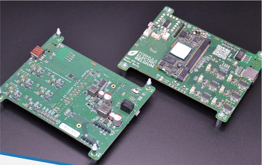
The finished ECU
Peripheral Components
First, we need to read all the sensors and control the motors and other actuators, like the brake light or cooling fans. For this we have six different CAN-busses that connect every system in the car together. For our ECU we decided to upgrade these to the newer CAN-FD standard, with up to 4 times more data transfer.
For the telemetry, we provided a module that can communicate with the team on the side of the track using the Zigbee protocol. Data-logging is possible using either the SD-card slot, or the USB-port.
For integration of autonomous systems, a Gigabit Ethernet port is placed. This can be used for communicating with autonomous sensors like a Lidar or camera’s, but also for communicating with other systems, like a PC handling the autonomous algorithms.
All these systems need a good power supply, so we provided 3 power lanes for all components. A 5V supply provides the power for the USB port and a 3.3V line supplies the rest of the board.
Lastly, this is a prototype, meaning that we need lots of options to debug our system. Status LEDs provide visual feedback, but a UART and JTAG port provide us with even more options to view the status of our system.
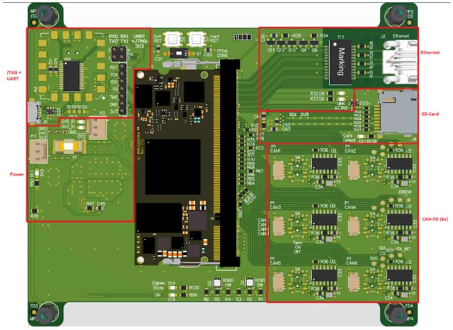
The top view of the PCB design
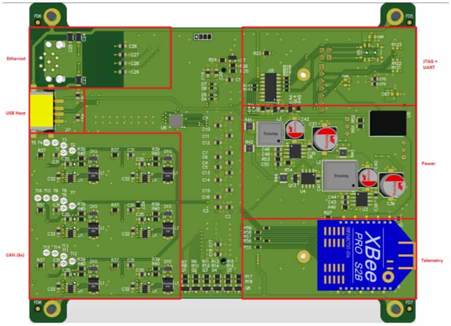
The bottom view of the PCB design
The Challenges for Formula Electric Belgium
This new ECU is one of the more complex PCBs used in the team. We were able to get most of the components working quite quickly. This was made possible by following some ground rules during the design.
Firstly, we made sure to follow best practices regarding signal integrity. The differential pairs signals of the ethernet, USB and CAN signals all have a defined impedance, calculated using the tools provided by the Eurocircuits website. We went for the defined impedance build-up to make sure that the impedances we calculated are manufactured correctly.
Secondly, we made sure that the design was compatible for automated assembly. Every component has mechanical layers defined in the design, indicating component centers, outlines, fiducials, and extra information that can help the assembler in its task. The automated assembly provided us with a more reliable PCB, so we could focus on the design of the system, rather than fixing issues that come with manually soldering hundreds of components.
Conclusion
Formula Electric Belgium is very proud of its prototype. We managed to create a fully functioning ECU, running a custom linux kernel on a self-designed PCB. This was mainly made possible because of the help of our partners and because of the teamwork between our partners as well. We learned a lot from Eurocircuits, Dekimo and Wurth Electronics for this design and we hope to continue doing so in the future.
![]()
For more information please visit formulaelectric.
Be the first to read all about our news and information. Follow us on