Hanze Racing Division in 2023
At Hanze Racing Division, HARD, they build a self-driving electric race car for Formula Student. HARD will be competing in the 2023 edition of Formula Student Netherlands in the electric class. Next year, HARD will be converting its current car, the HRD-05, to a driverless car and compete in the driverless class.
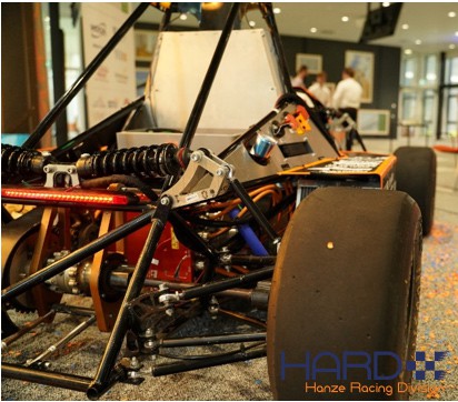
After many hours of engineering, the car is almost ready to race. The car uses a complicated electric system to make sure everything is safe and driving. At its center you can find the high voltage (HV) system, which powers our motor. So how do PCBs help us in this HV system?
Down below you can see the simplified schematics of our system. On the left we have our battery and on the right our inverter. When we are preparing to drive the car, we first press our activate button on our dashboard. This will send a signal to our first PCB, the activation logic.
When starting the car, the activation logic will close the precharge relay and negative AIR, slowly charging the inverter. The precharge PCB will measure the voltage on the inverter side; when it reaches 95% of the battery voltage, it will send a signal to activation logic, which will then close the positive AIR and allows full current flow through the system, but at the same time the precharge relay will remain closed.
These HV systems are very dangerous, which is why it is important to know when the HV in on. For this, we have two more PCBs. The first one is our voltage indicator. Our voltage indicator works entirely from within our accumulator container. Our HV DC/DC converter makes sure it brings the voltage from our battery down to 12V, so it can power our voltage indicator. It is important that this voltage indicator can work without our low voltage system, because it also needs to be able to check the accumulator container when detached from the car. When the indicator sees that there is HV in the system, which it checks right after our AIR+ relay, it will turn on a green light on our accumulator container.
The second PCB, the TSAL measure, checks is there is HV outside of the accumulator container. If this is the case, it will light the indicator on top of the car. The indicators of the voltage indicator and the TSAL will make sure we know when we can touch our HV system or Accumulator container or not.
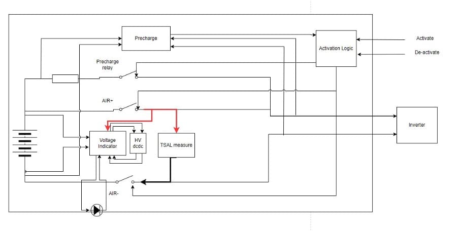
There are a lot more (safety related) PCBs in our car. They are essential elements that make sure our systems can measure and control to create a safe and driving electric race car!
![]()
For more information please visit the Hanze Racing Division website.
Be the first to read all about our news and information. Follow us on