SEMI-FLEX pool – Bare board & assembly services

A flex to install solution
Eurocircuits’ SEMI-FLEX pool is a solution for flex to install 4 or 6 layer PCB made entirely of FR4.
Unlike conventional flex-rigid PCBs, the flexing element is not polyamide but a thin FR4 core with two layers of copper specially treated to flex without cracking.
What’s Available
Bare Board or Assembled PCBs
- Bare Board or Assembled PCBs
- Bare Board PCBs in 7 Working Days* or Assembled PCBs in 12 Working Days*
- Standard lead times:
- Bare Board PCBs in 7 Working Days*
- Assembled PCBs in 12 Working Days*
- Shorter lead times are available in the PCB Calculator
- See Tables Below for Available Specifications
- No Tooling Charges
- No Minimum Order Charge.
- 100% Manufacturability Check Prior to Production
- PCB Configurator to check and upload design parameters before pricing
- PCB Checker to analyses your data before you place your order
- BOM and CPL analysis
What is SEMI-FLEX
SEMI-FLEX is a flex to install 4 or 6 layer PCB made entirely of FR4. Unlike conventional flex-rigid PCBs, the flexing element is not polyamide but a thin FR4 core with two layers of copper specially treated to flex without cracking.
Why use SEMI-FLEX
SEMI-FLEX is flex to install. Unlike polyamide, the FR4 core is not capable of continuous flexing.
However it will bend a limited number of times (typically 5 – see the technical specification below) at a controlled radius and to any angle.
This makes it an ideal solution where you need to mount two PCBs in a unit at an angle to each other. Instead of using connectors and cables or a composite flex-rigid PCB, you can design a single FR4 SEMI-FLEX PCB which can be safely bent a sufficient number of times to allow installation and subsequent maintenance as needed
Eurocircuits’ SEMI-FLEX pool
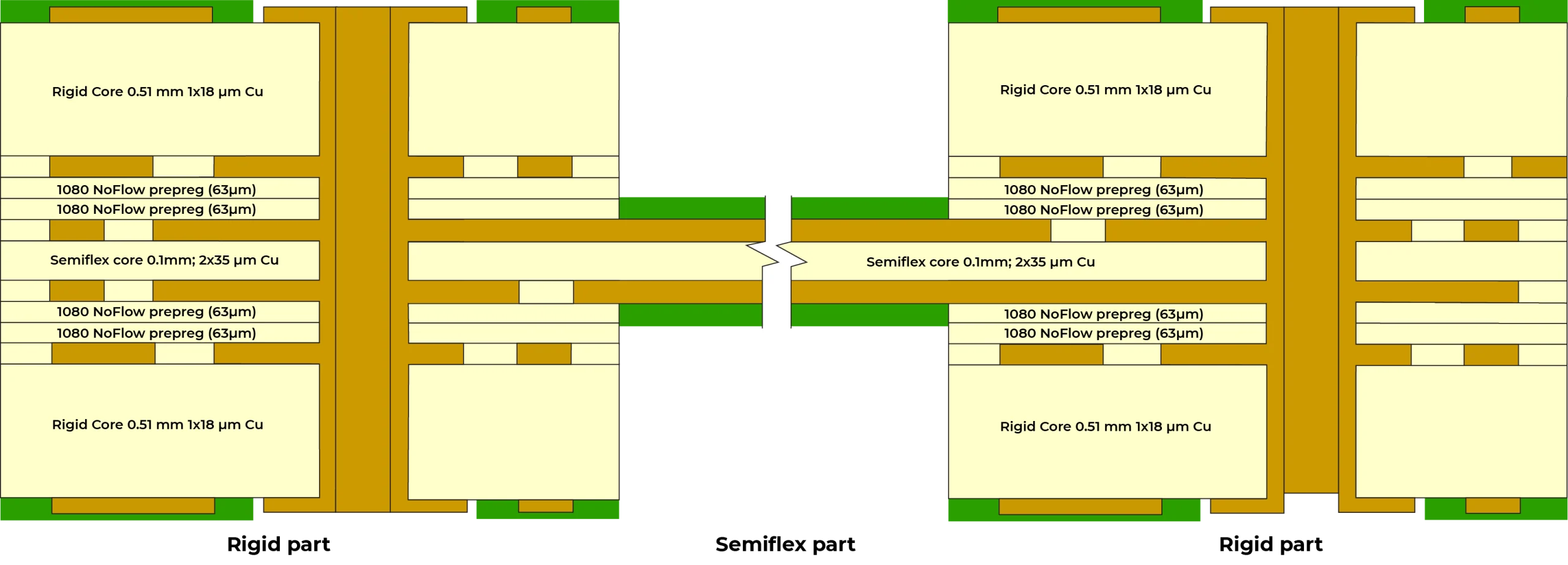
Eurocircuits’ 4 or 6 layer SEMI-FLEX PCBs use a 100 micron central core for the flex area, with 35 micron high-ductility copper foil on each side.
The stack is then made up on each side with a 510 micron FR4 core and two layers of no-flow prepreg (see the full technical specification below).
An alternative technology is to build a 2- or 4-layer PCB and then depth-mill the material away to leave a thin section as the flex area.
We have adopted the core solution even though it needs more operations and so is a little more expensive. It gives a symmetrical build and so a more stable PCB, while depth-milling is difficult to control meaning that the flex area may have an irregular thickness.
With a core-build we through-mill (rout) the prepreg before pressing. We can then rout the outer layers with any minor variation in cutter depth being absorbed by the void.
The core build makes it easier to design a main PCB with up and down sections or a final Z-configuration.
SEMI-FLEX PCBs are preferably supplied in a panel to avoid any damage during transport or assembly.
| SEMI-FLEX pool Service Parameters | |
| SEMI-FLEX Area | |
|
Minimum Bend Radius |
5 mm |
|
Maximum Bend Angle |
180° |
|
Maximum Number of Bends |
5 |
|
SEMI-FLEX length Calculator |
(2 x pi x bend radius) x (bend angle/360) For example, bending 5 times over an angle of 180 degree with a radius of 5mm requires a minimum length of the semi-flex part of 15,7mm
|
|
Minimum semi-flex length |
Minimum = 3.00mm |
|
Minimum semi-flex width |
Minimum = 3.00mm |
|
Copper thickness on SEMI-FLEX Core |
35µm high ductility copper |
|
Highest Pattern Class |
Class 6 – 150µm track/gap (to accommodate the bending) |
|
Drill Holes |
Not allowed  |
|
Slots and cut-outs |
Not allowed |
|
Corners in SEMI-FLEX Area Profile |
Minimum radius 1.00mm  |
|
Corner where a Narrow SEMI-FLEX Area Joins Rigid Area |
Minimum radius 1.00mm |
|
Recommended |
Use copper on both sides |
|
Recommended |
Use copper pour around tracks where possible |
| RIGID Area | |
|
Required |
Yes – At each end of the Semi-Flex Material |
|
Minimum Size |
Width of Semi-Flex Material or 5mm x 5mm whichever is the greater |
|
Material (rigid and semi-flex cores) |
|
|
Number of Copper Layers |
4 or 6 |
|
PCB Thickness |
1.55mm (see build map) |
|
SEMI-FLEX Core Thickness |
0.100mm |
|
Outer Layer Start Copper Foil |
18µm |
|
Min. Track Width/Spacing |
0.125mm |
|
Min. Finished Hole Size |
PTH 0.100mm NPTH 0.200mm |
|
Surface Finish |
Pooling – ENIG, IM Ag |
|
Soldermask |
Green |
|
Legend |
White |
|
Profile |
Break-routing or V-cut |
|
Slots and Cut-outs (milling) |
Tool sizes – 0.5, 1.2, & 2.0mm – in Rigid Area Only |
|
Advanced Technologies Allowed |
Pooling – Peelable mask, PTH on board edge, Round edge plating, Copper up to board edge, Heatsink paste, Via filling, Edge Connector Gold Non-Pooling – Carbon pads |
|
Advanced Technologies Not Allowed |
Blind & Buried vias |
|
UL Marking |
Not yet available |
|
Delivery Format |
Preferably delivered in a panel for safe handling |

| SEMI-FLEX pool Assembly Service Parameters | |
|
Number of Component Layers |
1 or 2 |
|
Quantities |
1 PCB and up |
|
Lead Time |
12 working days* (7 for manufacture and 5 for assembly) |
|
Minimum PCB Dimensions |
Width of Semi-Flex Material or 5mm x 5mm – whichever is the greater |
|
Maximum PCB/Panel Dimensions |
340mm x 440mm |
|
Assembly Type |
SMT – single or double sided THT – single or double sided SMT + THT Mixed Technology – single or double sided |
|
Components |
Passive Components – 0201 and higher Active Components – from 0,35mm pitch BGA – 0,4mm pitch and above |
|
Solder Alloy |
Basis SAC 305 Sn 96,5 Ag3 Cu 0,5 lead-free |
|
Solder Paste Stencil |
Laser cut (included in the assembly cost – not delivered with the assembled PCBs) |
|
Component Sourcing |
All Components Sourced by Eurocircuits (Components not sourceable by Eurocircuits can be supplied by the customer) |
|
Quality Inspection |
Visual inspection
Solder Paste Inspection (SPI) BGA Placement X-ray Inspection |
*Notes
- Subject to design meeting our IMS pool manufacturing and assembly specification and component availability.
- The price cannot be automatically calculated for a PCB containing more than 200 BOM lines or 1000 component placements, our engineering department will evaluate and send you an offer usually within 24 hours.
- These conditions are available in our calculator/Visualizer and will only be confirmed in our order confirmation.