De Creatieve STEM Shapes Tomorrow’s Innovators

Shaping the Future of STEM Bringing PCB design and electronics to kids together with Eurocircuits: the Dark Sensor & the Beetle Bot re-imagined
We’re excited to share some big news about our journey to make electronics accessible and fun for everyone. As a non-profit, our mission at De Creatieve STEM is to spark curiosity and a maker mindset through hands-on electronics projects. We believe understanding electronics is key in our modern world, and we’re committed to sharing this knowledge with people of all ages through our STEM programs.
To make this happen, we develop easy and engaging projects that involve PCB design and microelectronics. Our team of volunteer experts in electronics and PCB design is fundamental to our success. (A very special thank you to Herman and Yvon!)
A crucial part of our mission is ensuring that everyone, regardless of their background, has access to this knowledge. That’s why the financial support from Eurocircuits is so important; it helps us democratize access to these projects. Not only do they provide financial support, but their experts also play a role by performing final checks on our design files to ensure everything is correct. We also hope to inspire young people to consider careers in electronics beyond just programming, showing them that hardware and design can be a lot of fun.
This year, we’ve focused on two main projects: the Dark Sensor and a custom PCB for the Beetle Bot. We wanted to create a kid-friendly soldering kit for the Beetle Bot, a well-known open-source project, making it perfect for STEM camps and after-school programs where time is often limited. In this blog post, we’ll dive into the details of both of these projects.
Dark Sensor: Igniting a Passion for STEM
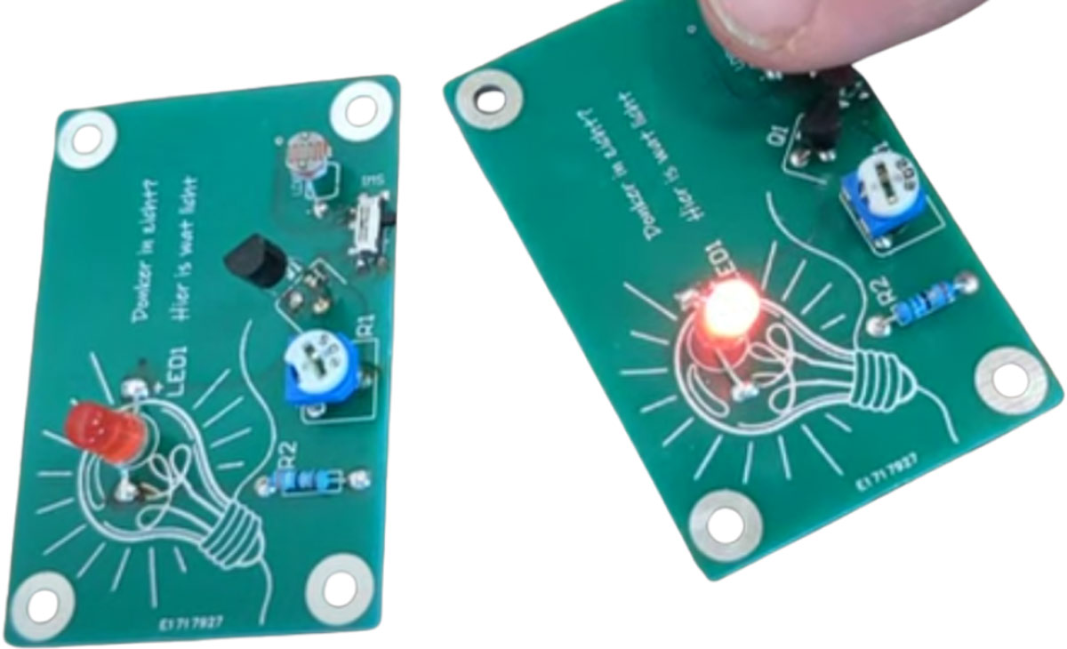
At our STEM academies and projects, we’re dedicated to inspiring the next generation of innovators. We aim to ignite a passion for electronics and STEM subjects in both young and seasoned learners. To achieve this, we developed our own.
DarkSensor PCB (Printed Circuit Board). This compact yet powerful circuit detects changes in light, making it an ideal starting point for anyone new to electronics. It serves as a tangible bridge from theory to practice, helping people grasp concepts like sensors, components, and the importance of a well-designed circuit.
What is a Dark Sensor ?
- A sensor that is activated by a lack of light.
- It is a simple and powerful concept, which uses a transistor (BC 547 NPN) as a switch to automatically turn a light system ON and OFF.
- It automatically switches ON lights when the sunlight goes below a certain value, for instance, in the evening.
- It automatically switches OFF lights when sunlight falls on it, for instance, in the morning, by using a sensor called LDR (Light Dependent Resistor) which senses the light just like our eyes.
What could a DIY set look like and how do you work with kids?
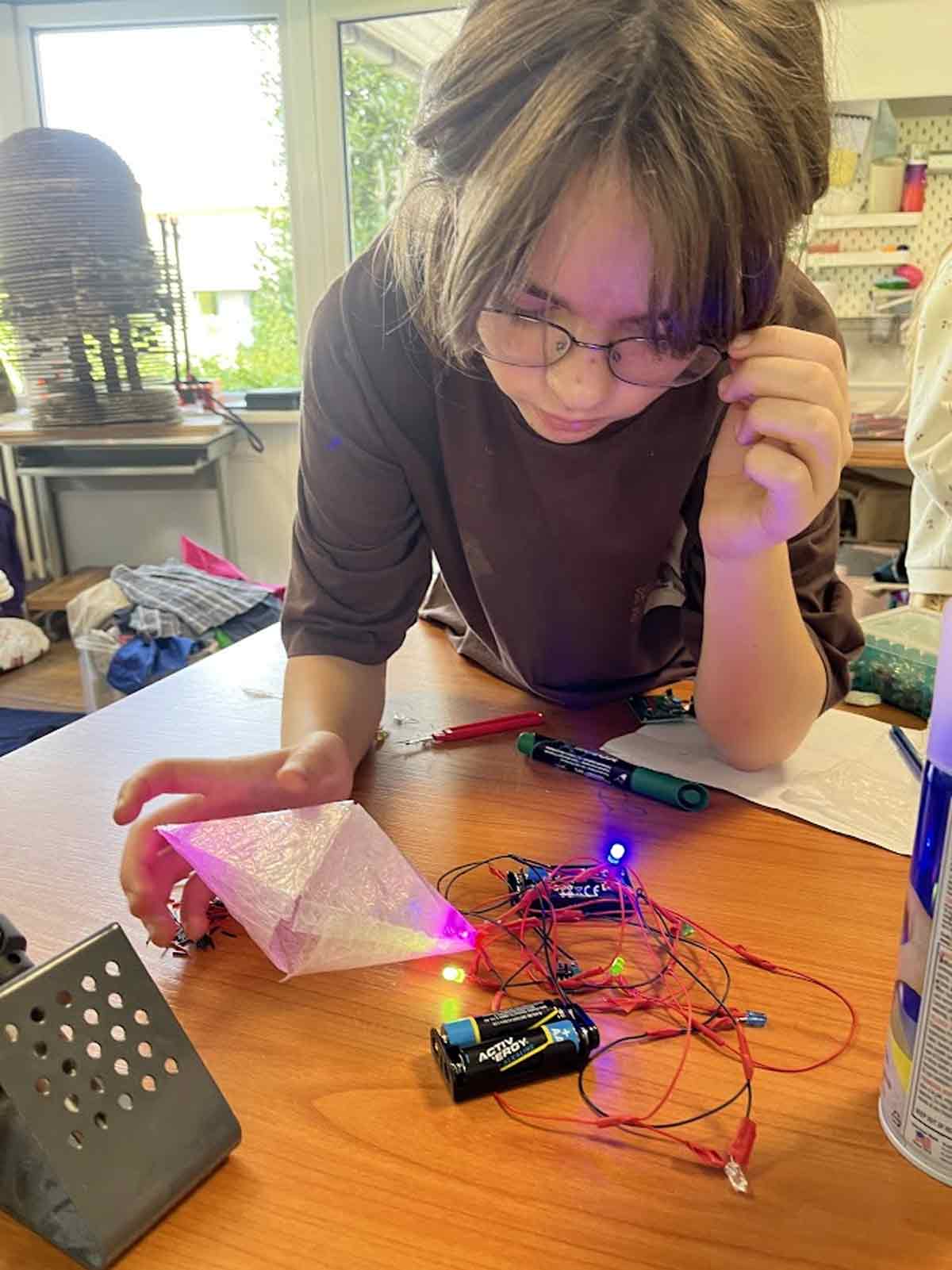
In our enthusiasm to bring kids in contacts with (real) electronics over the years we have experimented with different set ups and even though chaos can be quite inspiring we realised that we needed something more reliable than these situations.
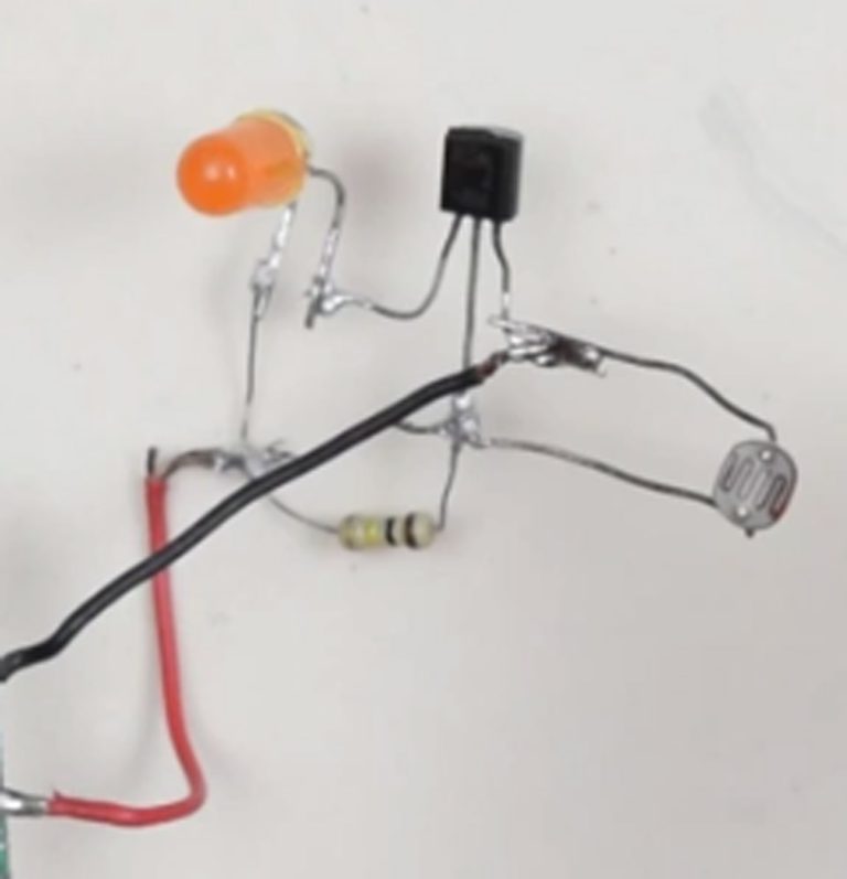
which are both time consuming in debugging when busy with a room full of enthusiastic kids

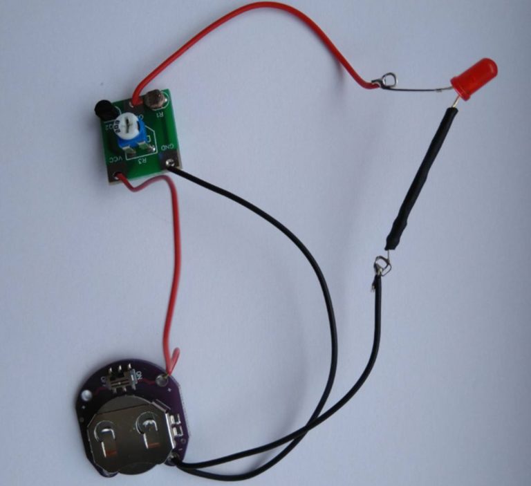
From a heap of cables to a neat PCB
To bring order in the chaos, to make activities manageable and to bring high level STEM principles to unskilled users we decided to design a custom PCB for this project, so that we have a kid friendly soldering kit. Easy to assemble and comfortable to debug when needed!
A Vision Realized with the Support of Eurocircuits
Designing a custom circuit board is one challenge, but bringing it to life through professional manufacturing is another. Thanks to the incredible support of Eurocircuits, we’ve been able to transform our designs into functional, high-quality PCBs. More than just a supplier, Eurocircuits has become a valued partner in our mission to advance STEM education.
Our DarkSensor PCB is more than just hardware; it’s a gateway to a world of possibilities. By providing hands-on experience through projects like these, we’re laying the groundwork for a future filled with innovation.
Technical Details
The circuit uses a Transistor (BC 547 NPN) as a switch to automatically turn the LEDs on and off. By using a sensor called a LDR (Light Dependent Resistor) that detects light, the lights can automatically turn on when the sunlight falls below a certain threshold. The lights then automatically turn off when sunlight hits the LDR. No manual operation is needed to switch them on and off! You can also control the sensitivity with a potmeter.
The circuit uses about 2 mA of power in standby mode (when the LED is off). Since a 3V coin cell battery has about 100 mAh, the battery would last about 50 hours in standby mode. Because the LED also consumes power when it’s on, the average battery life will be slightly less than 50 hours. If you want your battery to last longer, you’ll need to reduce the standby power consumption. You can do this by using an LDR with a higher resistance or by adding a 1kOhm resistor between the negative pole of the battery and the LDR.
Bill of Materials
- BC547
- 20k potmeter
- 50 ohm resistor
- LDR
- 3V coin cell battery
- LED
- Switch
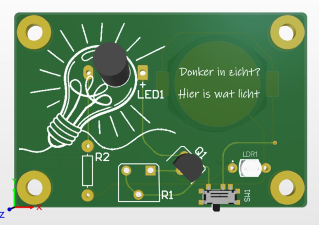
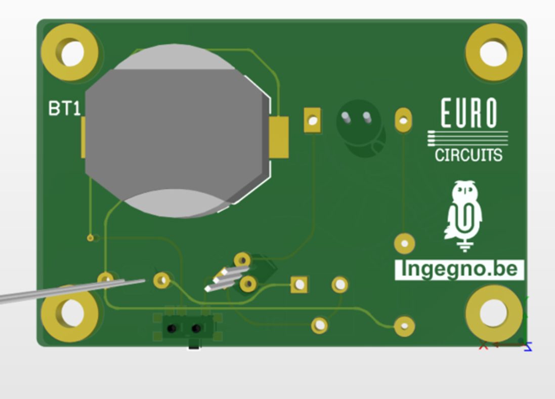
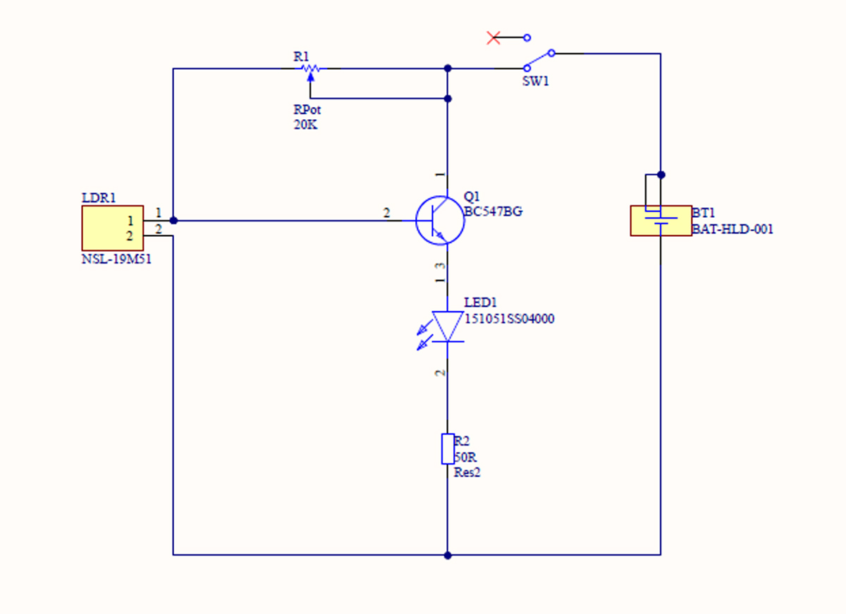
Scheme
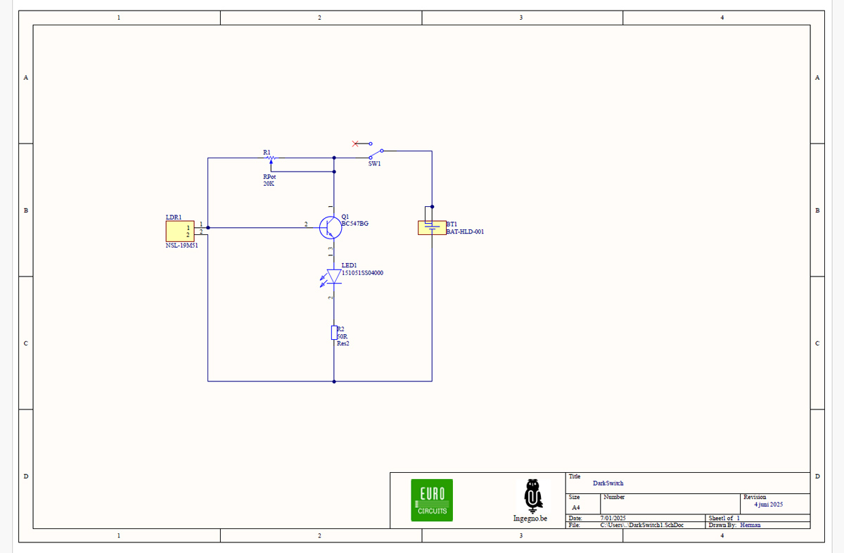
How does it work?
The transistor Q1 is the switching element. It switches the LED, LED1. To limit the current and extend the life of the battery and the LED, R2 is placed in series with it. This limits the current to a few mA. This also reduces the light intensity of the LED, but the LED will not break as quickly.
The transistor T1 is controlled via the base (Pin 2). The voltage on the pin is transferred to the LED and the resistor. The current is amplified. The input circuit is a voltage divider R1 (potentiometer) with the LDR. When no light falls on the LDR, its resistance is high, and the voltage on pin 1 of the LDR and on the base of Q1 will be high. The LED will light up. When light falls on the LDR, its resistance is low, the control voltage on the transistor is also low, and the LED will light up less. It might even turn off completely. You can adjust this tipping point (or the light level) with the adjustable resistor R1.
The Beetle Bot: A Kid-Friendly Soldering Kit
The Beetle bot PCB is a re-interpretation and re-invention of a well known open source project by robomaniac. The original Beetle Bot is a very simple and efficient robot that uses no electronic components to avoid obstacles in its path. Instead, it uses two SPDT (Single Pole Double Throw) switches to avoid obstacles by reversing the opposite motor to pivot and free itself.
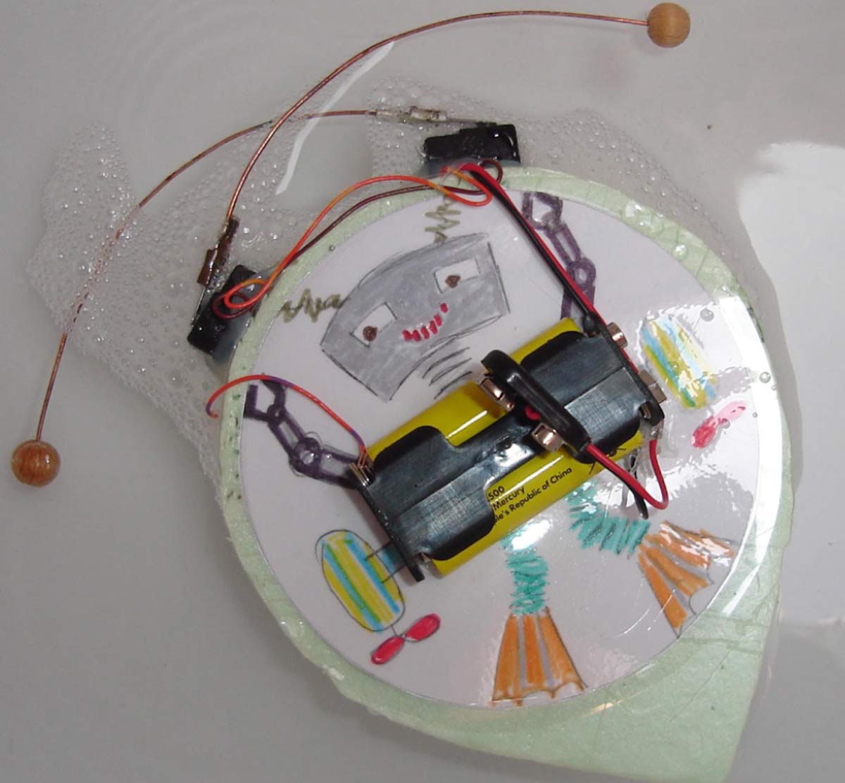
The cute robots are always a hit with the general public andwork well when the goal is to spark curiosity. But both the first and second version are prone to building/wiring errors when dealing with groups in STEM clubs. Even though the making process is fun, it is time consuming and unfortunately limited available time is the most common constraint we have to deal with. This led to the idea of creating a custom PCB (Printed Circuit Board). We wanted to create a kid-friendly soldering kit for this project, making it perfect for STEM camps and after-school programs where time is, as said, often limited.
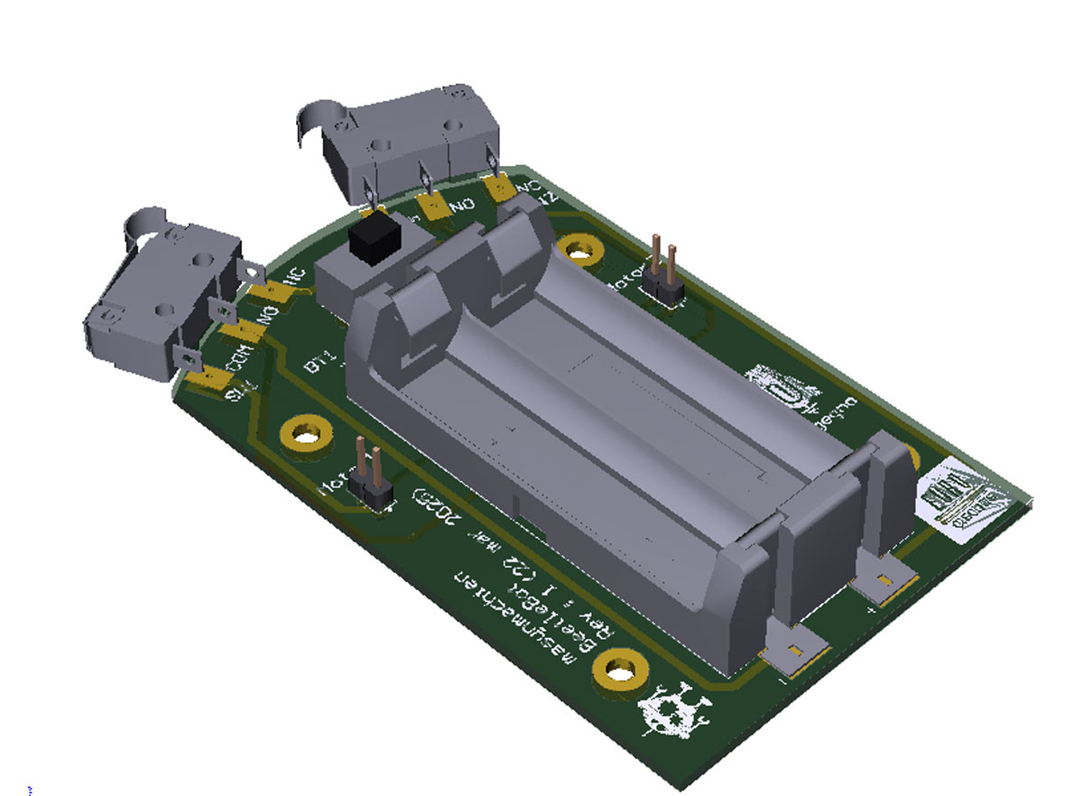
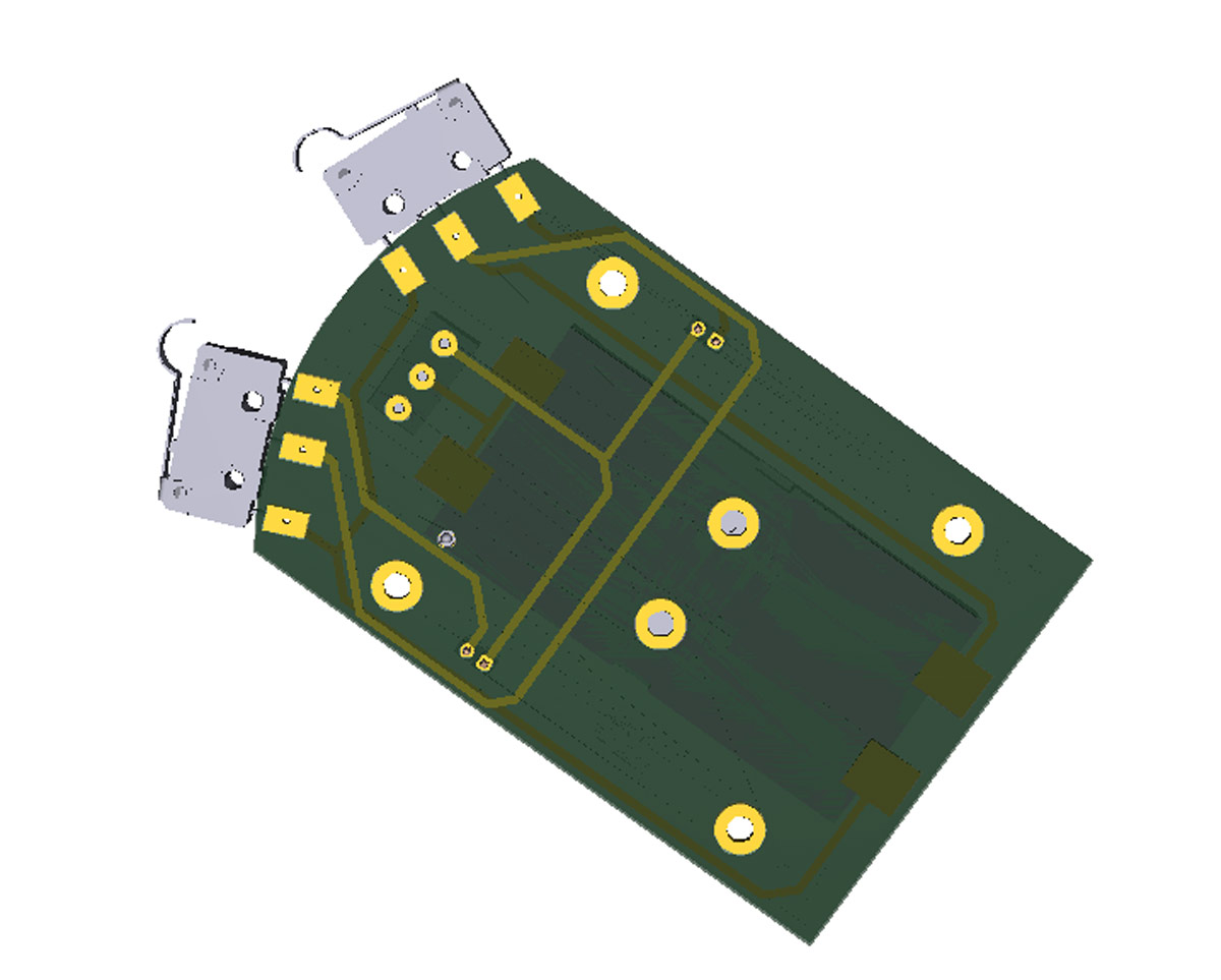
Technical Details and Components
The custom PCB was designed as a joint work with Masynmachien

The scheme is as follows
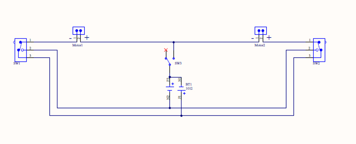
The Beetle Bot has two motors, Motor1 and Motor2, that can spin forward or backward. Motor1 is connected to a positive source (BT1/P1) via switch SW1, causing the motor to spin in one direction. If the limit switch is activated, the motor will see a different battery voltage (BT1/N2) and spin in the opposite direction. This also applies to the Motor2 circuit. The motors are always on.
SW3 is included to turn off the Beetle Bot. However, in this first PCB design, there was a small issue: even if SW3 was off, the motors could continue to run in a specific position of SW1 and SW3. This problem was discovered after the first tests when a Beetle Bot was put away in a backpack. This led to the creation of a new version of the Beetle Bot.
Our second version has a switch (SW3) that turns off all the battery cells. Additionally, two sets of solder pads were added to the PCB, making it easier to connect the motors.
For more information please visit the Ingegno website.
Bring your product to market on time and within budget – join the Eurocircuits Community


![]()

