Da Vinci Satellite: Student CubeSat for Space Education
The Da Vinci Satellite is an educational project, both in its output and in its development. The project’s goal is to inspire the younger generation and to enthuse them for space exploration through a series of educational lessons and direct interaction with the satellite’s payloads. The project’s development is also focused on education, as the satellite is entirely developed by students for students.
The Da Vinci Satellite team has been sponsored by Eurocircuits from the early designs of our solar panels to our most recent Printed Circuit Board (PCB) designs. The team is now in a delicate phase: right at the finishing design touches, and about to begin more intensive and integrated testing campaigns. This means that we will finalize our designs, order material, and simultaneously develop protocols and procedures to ensure the safety of our software, hardware, and team members during testing.
On-board subsystems
In the past two academic years, the team has been developing testing boards and flight components, some of which are soon going to be part of a space qualification campaign. On board of the satellite, there are three main in-house developed subsystems: the Dice Payload, the Bitflip Payload, and the Command and Data Handling subsystem’s data board.
The Dice Payload
The Dice Payload is a mechanical payload that was designed with primary school children in mind. It consists of five dice that are thrown in microgravity, along with a camera that takes pictures of them. A sweeper shuffles the dice and then clamps them. By clamping the dice, it is possible to take a picture of them with the Earth seen from space in the background, which is then later downlinked to the ground station.
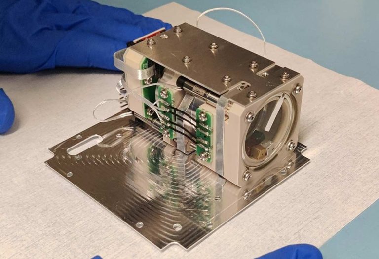
The clamping and sweeping are actuated using an Arduino and a motor driver, which are connected and the sweepers’ motors via a PCB from Eurocircuits.
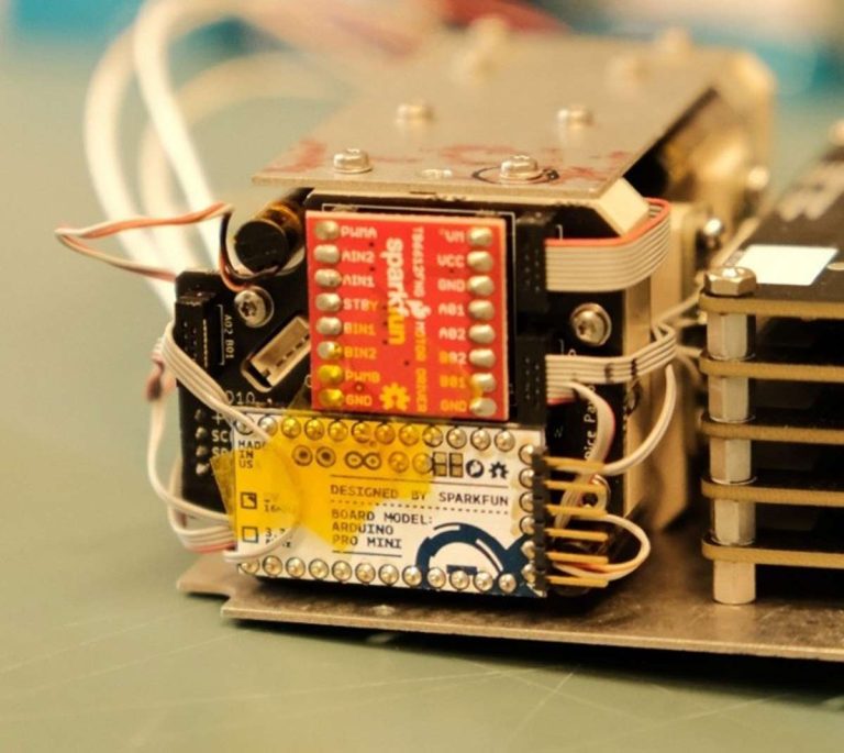
The Arduino also needs to coordinate the LEDs, which will assist when taking a picture of the dice. Additionally, it needs to stop the motors from clamping the dice to prevent them from stalling. Due to the required coordination, there are multiple connectors on the PCB running to other PCBs, such as the LED PCB and the limit switch PCBs.
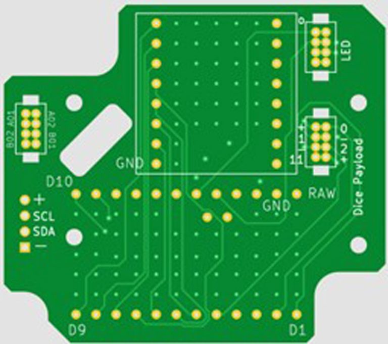
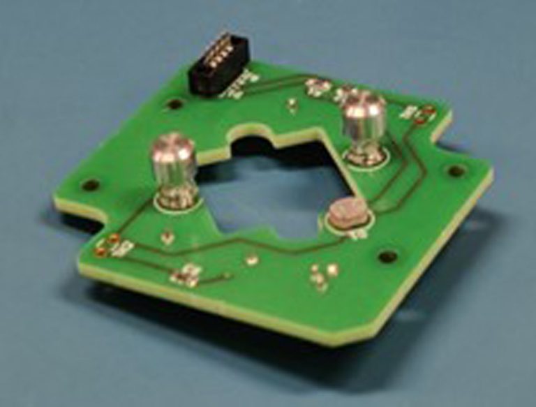
The LED PCB is connected to the Arduino via the top right connector through a ribbon cable.
The hole in the middle of the LED PCB is for the camera. The PCB can host a transistor, two LEDs, and the required resistors on the LED PCB.
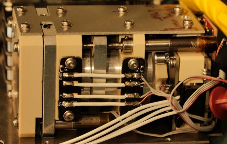
The Arduino is connected to two sets of limit switches via a ribbon cable. The limit switches detect when the clamp (the aluminum part in between the PCBs) is at the start or at the end of its stroke.
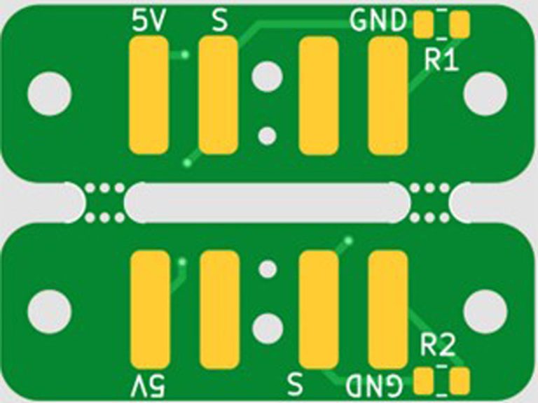
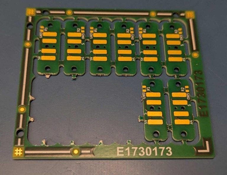
There is a spot for a resistor on each PCB. The limit switches are soldered on the backside and slot into the PEEK slabs to which the limit switch PCBs are mounted.
The Bitflip Payload
The Bitflip Payload is designed for advanced students with an interest in programming. It consists of five stacked printed circuit boards (PCBs) equipped with a series of memory chips. These memory chips are intentionally left unprotected from cosmic radiation, which can cause random bit flips within the stored data. As a result, images saved on board become distorted. Students can then analyze and decode these altered images by applying concepts taught in our educational lecture materials.
PCBs from Eurocircuits will be used in our Qualification Model and Flight Model for the Bitflip Payload. Currently, we are assembling the Qualification Model for the Bitflip Payload, which, together with Dice Payload Qualification Model, will undergo vibration and thermal testing in a few months, to simulate the conditions of a rocket launch and the harsh space environmental conditions.
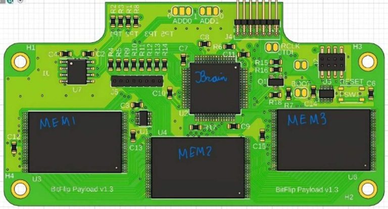
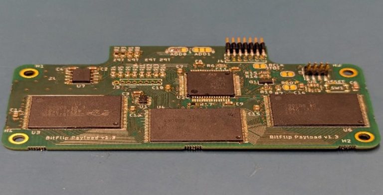
The figures above depict a single Bitflip PCB. Each board contains one primary control chip, referred to as the “brain”, along with three memory modules. The control chip manages and operates the payload, while the memory modules store the images uploaded to the bitflip payload. These stored images are vulnerable to cosmic radiation, which can alter the memory bits and result in distorted images being relayed back to students.
The complete bitflip payload on the Da Vinci Satellite consists of five PCBs stacked together using male/female pin headers. Four critical connections link the boards: SDA and SCL for I²C communication, VCC (3.3V), and Ground. Power is supplied by the On-Board Computer (OBC), while I²C communication is managed through the payload manager.
Each PCB’s microcontroller is programmed using the STM32Cube software. By utilizing the programmed microcontroller, it is possible to calculate the number of bit flips that occur on the memory chips by comparing the uploaded image with the received, distorted version.
The memory modules use SRAM technology, which requires a constant power supply to maintain stored data. Because SRAM is sensitive to cosmic radiation, disruptions in its memory bits directly contribute to the distortion of the stored images.
The Command and Data Handling Subsystem
The Command and Data Handling Subsystem (CDH) is the satellite’s brain. It hosts three microcontroller units to operate the payloads and the rest of the satellite bus. It also hosts a GNSS receiver, which is an additional payload provided by TU Delft that the satellite is carrying. The data board, CDH’s PCB, manufactured and delivered by Eurocircuits, plays a crucial role in the success of our satellite mission as it ensures that the electrical connections can transport data and power to the correct subsystems.
In most satellites, the central processing unit is referred to as the On-Board Computer (OBC). In the Da Vinci Satellite, this role is fulfilled by the CDH. It earns this distinct name because, unlike typical designs, it hosts not one but three OBCs:
- Two DPQ-TUD-TN-OBCs, designed for and flown on the Delfi-PQ satellite.
- One HT-CP400.85 OBC from Hyperion Technologies.
Each of these OBCs serves a specific purpose within the Da Vinci Satellite architecture:
- One DPQ OBC acts as the main flight computer, running the satellite’s primary software.
- The second DPQ OBC functions as a dedicated microcontroller for the GNSS receiver payload, a design choice made because the GNSS receiver and DPQ OBC were originally developed to operate together.
- The Hyperion OBC serves as the payload manager, acting as an intermediary between the payload bay and the main OBC.
Beyond processing and control, the CDH provides all the necessary interfaces to connect each subsystem to its respective OBC. It also includes interfaces with sensors all over the satellite that track the satellite’s health status, such as temperature readings and power production metrics.
For development and maintenance, the CDH is equipped with an additional debug interface. This debug port allows engineers to reprogram or update the satellite’s systems right up until launch through an external connector. It can also be used during thermal vacuum testing to receive data—an essential feature since RF communication cannot be used inside a vacuum chamber.
Electrical Ground Support Equipment
Our team uses a series of PCB designs for testing purposes. These PCBs are called Electrical Ground Support Equipment EGSE, which we use to test, monitor, and communicate with the satellite before launch. It is a vital part of our test campaign, allowing us to build up the so-called FLATSAT – a flat configuration of all our satellite subsystems laid out next to each other on a table with all wires and power lines connected. This is a crucial step to verify the software and hardware interfaces between the building blocks of our satellite.
The new EGSE PCBs have been designed to replicate the physical and electrical stacking of the assembled satellite. In the actual satellite, most subsystems are interconnected through a PC104 stack connector, which ensures that each subsystem is linked to the main data bus on the data board and receives power from the Electrical Power System (EPS).
These new EGSE boards mimic that same setup, allowing engineers to test individual subsystems or connect multiple subsystems using several boards. This provides a major advantage: it enables testing of the satellite’s full integration and communication without the need to physically assemble the entire spacecraft.
Each EGSE board includes power switches, allowing the use of an external power supply when testing systems independently of the EPS. In addition, the boards feature a slot for an MSP LaunchPad, which can be used to run the satellite’s software during tests without requiring the data board.
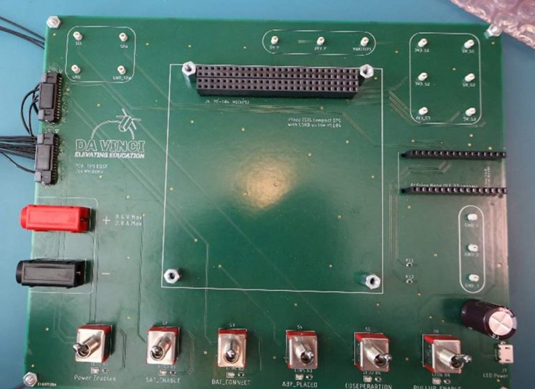
When testing a single subsystem, it can be mounted directly on top of an EGSE board via the PC104 connector. For testing multiple subsystems or operating in a FLATSAT configuration, each subsystem is installed on its own EGSE board. The boards are then interconnected through large side connectors, known as the inter-EGSE connectors.
This modular approach allows for flexible, efficient, and realistic testing of satellite subsystems, making it easier to identify issues early and streamline the integration process.
Mission outlook
For a student-developed satellite, reliability is everything. Space hardware must survive:
- Violent rocket launch vibrations.
- Extreme temperature swings in orbit.
- Years of exposure without repair.
Eurocircuits’ PCBs provide the high precision, durability, and consistent quality required for such missions. Their boards reliably support our work from the first prototype to the final flight-ready designs. The Da Vinci Satellite is now in the final stages of design and testing. Soon, our payloads and PCBs will undergo space qualification campaigns – vibration, thermal vacuum, and functional testing – before integration and launch.
Thanks to Eurocircuits’ support, our team is not only building a CubeSat but also inspiring the next generation of scientists, engineers, and explorers. Once in orbit, the Da Vinci Satellite will beam down data and images that students can analyze, turning our CubeSat into a flying laboratory for schools and universities.
Our team looks forward to sharing results, launch updates, and educational materials with the wider community and welcomes educators, students, and industry partners to join our mission of elevating education!
For more information please visit the TU Delft Da Vinci Satelite website.
Bring your product to market on time and within budget – join the Eurocircuits Community


![]()

