Defined Impedance Calculators

There are many different Impedance calculators for PCB designers to use, some are free such as the one available to Eurocircuits customers and some you need to pay for a licence or a monthly subscription. The aim of them all is to provide the necessary track/gap and isolation values for the layout and manufacture of your PCB. The interfaces vary from one to another as does the way you input the parameters that are used by the calculator and this is where a user must take care. Since the very successful launch of the Eurocircuits DEFINED IMPEDANCE pool service we have received feedback that results between our calculator and others varies. This is something that we took very seriously and launched an investigation to establish why there was a difference.
What we discovered

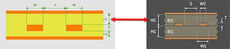
In addition, the H2 value in the other system is actually equal to H1 + T in our calculator as above.
Therefore, adding the same values for H1 & H2 in the Eurocircuits calculator compared to another may very well deliver different results, as the corresponding input parameters may differ.
To verify that the Eurocircuits calculator provides the correct results we ran several tests:
- Firstly, we used the same parameters in our calculator and the Altium calculator and as expected the results we different.
- We then corrected the parameters used in the Altium calculator to what they require (e.g. H1+T) and the results were extremely close (Zdiff = 100.035E vs 99.146463E).
It is important to use the correct dielectric constant (εr) value for the selected material. This value will change depending upon the selected frequency. In the Eurocircuits calculator all the known values are automatically updated based on the selected build-up. Another point to be aware of is how the calculator generates the results. Is it calculated using the correct formula or simply using a known ‘Rule of Thumb’ equation? For example, a ‘Rule of Thumb’ equation for a Differential Impedance value is 2x that of the Characteristic Impedance value. This is only a rough and non-mathematical value which may vary significantly from the real value. It is important to check how these values are derived?
Conclusion
When using an impedance calculator, you must ensure that the actual values entered, correspond to the parameters required and are not simply copied from one calculator to the next:
- Eurocircuits’ Impedance calculator uses real values as defined in the supplier’s data sheets.
- Eurocircuits also calculates the correct Differential Impedance values using the correct formula and not a ‘Rule of Thumb’ method.
Finally, all calculators provide theoretical impedance values as they cannot take in to account the variables and tolerances of the manufacturing process. This means that whilst the calculator gives you a value, the actual value measured on the PCB may well be different.
It is Eurocircuits’ experience that the measured values on the PCB are within a ±10% of our calculated values.
To find the Impedance Calculator in the PCB Visualizer, click on the button ‘Impedance Calculator’ as shown in the image below.

See also:
Bring your product to market on time and within budget – join the Eurocircuits Community


![]()

