User Guides
Our User Guides provide step-by-step instructions on how to use our free online smart tools and other available software.
There are 3 types of holes in a PCB, Plated Through Hole (PTH), Non-Plated Through Hole (NPTH) and Via Holes, these should not be confused with Slots or Cut-outs.
Tool lists for drill files are ALWAYS set as as the finished hole sizes (ENDSIZE) when input into our CAM system..
The drill bits used for the manufactured PCB’s are in increments of 0.05 mm.
We will convert the drill sizes in your drill files or tool lists into millimetres and then round them to the nearest 0.05mm.
For example:
The same rule applies for metric drill sizes these will rounded to the nearest 0.05mm.
Please provide separate drill files for plated (PTH) and non-plated (NPTH) holes if possible.
If this is not possible it is important to specify different tools for PTH and NPTH holes and mark clearly which are for PTH and which are for NPTH.
When no PTH/NPTH information is supplied we will use the following rules to determine PTH/NPTH:
All Via Holes are Plated Through Holes.
By default, Finished Hole sizes (ENDSIZES) equal to or smaller (≤ or <=) 0.45mm are defined as VIA holes.
You can adjust this default value for Via Holes in the PCB Configurator – Technology section by changing the value of the parameter Holes <= may be reduced.
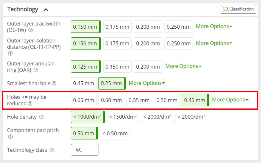
Holes of components (leads or mountings) or any hole of which the Finished Hole size (ENDSIZE) is ≤ the value set in the parameter Holes <= may be reduced in the PCB Configurator – Technology section will be automatically considered as Via Holes and maybe reduced by up to 0.30mm to solve possible annular ring issues on these holes.
To avoid this please follow one of the solutions below:
To allow for the plating in the hole we drill holes at a larger size (drill over-sizing).
The conversion rules from finished hole ENDSIZE to production TOOLSIZE are:
TOOLSIZE = ENDSIZE + 0.100mm (4mil)
TOOLSIZE = ENDSIZE
These are our standard tolerances that apply to the ENDSIZE of the drilled holes.
ENDSIZE(mm) |
Standard Tolerance(mm) |
||||
|---|---|---|---|---|---|
– |
+ |
Tolerance Range |
|||
| Hole | PTH | ≤4.00 | 0.10 | 0.10 | 0.20 |
| >4.00 | 0.20 | 0.20 | 0.40 | ||
| NPTH | ≤4.00 | 0.05 | 0.05 | 0.10 | |
| >4.00 | 0.10 | 0.10 | 0.20 | ||
When no tolerances are specified in your data, we will produce according to our standard tolerance specifications above.
If you require tighter tolerances please clearly indicated this in the mechanical layer and tool list, please note this may increase the cost of the PCB.
Any drilled holes that overlap the board contour will be handled as detailed below.
PTH holes with copper pads will be treated as “plated holes on the board edge” or “Contour Cut PTH drills” and should be clearly indicated in the mechanical layer.
NPTH holes without copper pads will be treated as part of the board outline.
Plated holes overlapping the board edge are not available in the PCB proto service.
Do not overlap drill holes as this may cause drill bits to break and may result in small pieces of material remaining in the hole barrel.
These may then cause voids in the plated hole.
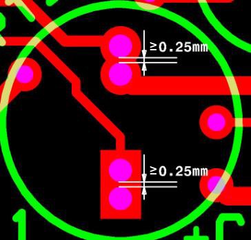
The minimum drill hole to drill hole distance is 0.25mm (10mil), this is measured edge to edge of the drill TOOLSIZE.
Do not use overlapping drill holes to define slots.
See section Mechanical Layer for the correct way to indicate slots and internal cut-outs.
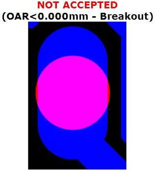
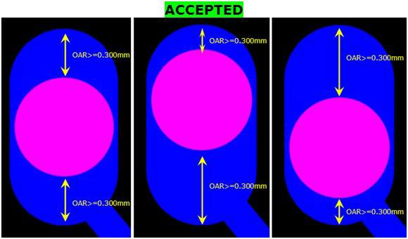
Drilling holes in oblong pads requires additional rules to ensure the connectivity of the pad is maintained.
The rules for annular rings of oblong pads are NOT different from round pads, but we allow some exceptions to these rules.
Oblong pads with NPTH holes
Oblong pads with PTH holes
The measurements below are taken from the production TOOLSIZE.
 |
 |
 |
 |
The hole may not be positioned in such a way that it could disconnect the pad from the track.