Formula Racing Miskolc

Formula Racing Miskolc is proud to welcome Eurocircuits as a team sponsor in the 2022 season. The company helps the team’s work with manufacturing high-end PCBs for developing a reliable electrical system and achieve good results during this season in the Formula Student competition series. We got a chance from Eurocircuits to introduce our team so taking the opportunity we share some major information about our team and the Formula Student competition series which can be read below. Formula Racing Miskolc is an initiative group of volunteering students where team members can gather extensive understanding and experience in the automotive industry and various fields of motorsport. They can learn the true meaning of teamwork, as well as use their knowledge in practice. The project provides an opportunity to become familiar with the usage of the most advanced technologies, as well as offering an indirect way to the industrial companies for the students who are involved. The team members are students of the Faculty of Mechanical Engineering and Informatics, Economics and Materials Sciences, who participate in the basic and master’s degree program of the region’s most significant institution of higher education and several professors and PhD students help our work. Besides providing the human resources, the University of Miskolc also provides the operation for the Formula Racing Miskolc with significant professional, infrastructural, financial support, and personal relations. The interests and extra activities of the team members include the automotive industry and there are several national and regional scientific students’ competitions as well as thesis works to prove it. It is natural that the members of the Formula Racing Miskolc are willing to invest their free time into research and development of the project, proving their dedication to and success for the Formula Student movement. The goal of Formula Student is to design, construct and introduce a formula racing car to a conceptual market and to race that car in several international racing events with the help of all members who have a legal student status. The organization ensures the team members gain valuable insights in their field of expertise and could build channels which enable smooth communication between the students of Formula Student and the supporter companies of the movement. These competitions are held in several countries across Europe, the most notable ones are Germany, England, Austria, and Spain. An average competition takes up to four days, which consists of two days of scrutineering and assuring that the car complies with various security rules. If it meets all these regulations, the vehicle will be allowed to take part in the next two days events. These can be sorted into two main groups: static and dynamic. Static events are presentations which include defending the engineering design, presenting a business plan and cost analysis. These give 40% of the total scores. Dynamic events include the “Acceleration”, the so called “Skid Pad” which tests the suspension dynamics of the car on an “8” shaped track, and the “Autocross” which examines the car’s performance on a specific section of the racetrack during measured lap time. Finally, the “Endurance” event where the overall time performance and fuel efficiency of the vehicle are taken under scope on a 22 km long track. We would like to thank Eurocircuits for the many electrical circuits they provide for us which serve reliably in our race car.Formula Racing Miskolc
Formula Student
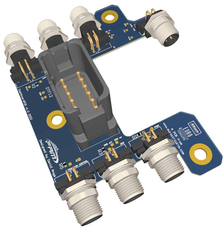
Dashboard PCB
This PCB is designed to make the buttons and switches on our dashboard part of our harness in a more organized way. This was achieved by giving each button a separate M12 circular connector and a common M12 connector for the water pump and fan switches. The circuit introduces these separate connectors into a 12-pin DT connector, make the harness more compact and easier to assembly and disassembly. In addition, we had to place ballast resistors for the LED indicator light on our buttons, because they operate at 3V. The indicator function for these LEDs was used to indicate the status of our emergency stop circuit (it is lit when the circuit is not activated, it is not lit when it has been activated). The shape of the board necessary because it is mounted the back side of the Motec C125 and provides access to the Superseal 1.0 32 pin header.
We use test point for manufacturing test and assembly test. We can test the PCB after soldering and the buttons/switches/ after we assemble it.
We don’t use box for the PCB to reduce weight but for water resist we clear coat it. As it is in a protected place in the car and the connectors are sealable it is enough protection against water for this simple board.
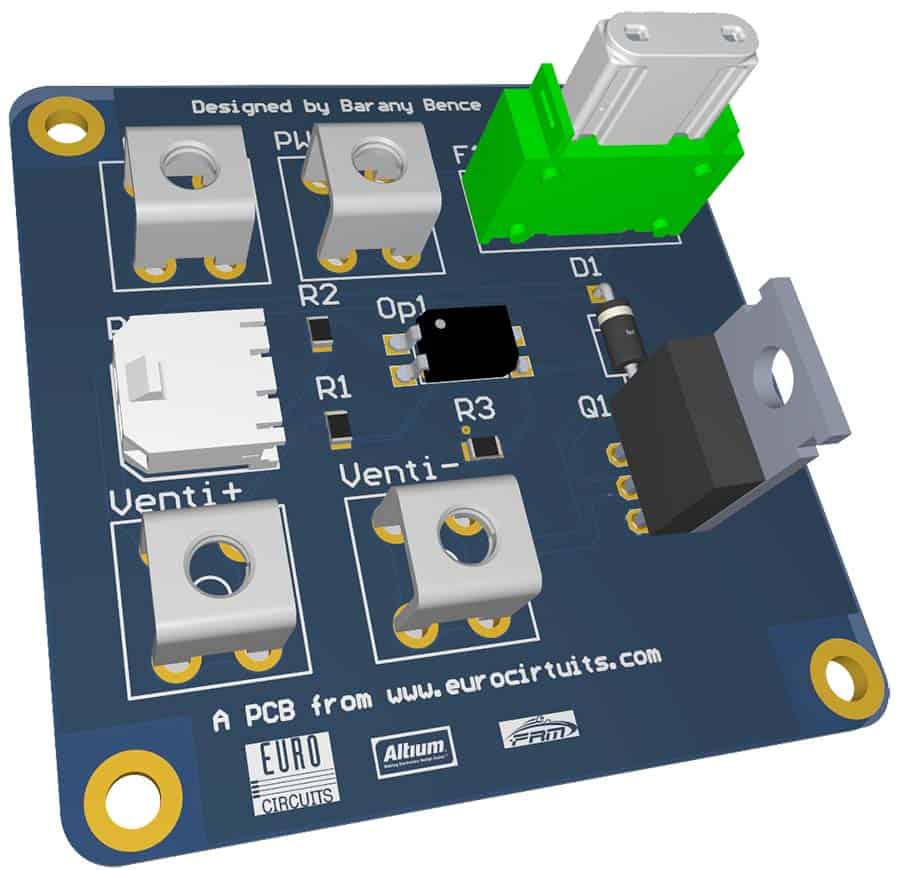
PWM Driver
This PCB is designed to control the speed of our race car’s water cooler fan. The thought arose when we had some issues with the water-cooling system, and it turned out we start the fan too late. It was the point we decided we want to control the fan speed with PWM. Our dashboard can do that but of course we cannot control it directly from the output of the C125 we use.
Looking at the PCB we can see four power connectors. 2 is for the 12V input and 2 is for the fan output. The small micro fit connector is the PWM input. Going forward we can find a resistor in series with an optocoupler. The resistor sets the input current of the LED. The optocoupler is separating the 3.3V and 12V systems. On the output of the optocoupler there are 2 resistors, their purpose is to divide the voltage and set the appropriate amount on the FET’s gate pin. This way we can open and close the FET as the PWM goes High and Low. The FET this way is obviously act as an electronical switch, the diode is in parallel with the Drain Source pins, it is a flyback diode to avoid the possible reverse voltage spikes coming from the fan’s inductivity. Finally, we placed a fuse on the PCB rated for the fan to avoid a possible short circuit in case there is a problem with the fan. We thank our sponsor Eurocircuits for the support and the fast and precise manufacturing of our PCBs. Without them we couldn’t maintain the quality we always try to achieve.
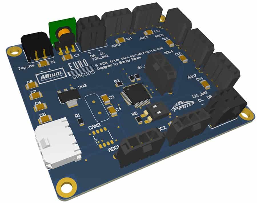
Telemetry Master
This is our telemetry systems master device’s board. It is quite the same as the slave, but with an extended set of tasks. The heart this time is an STM32F446. It is a bit more robust and have a few more periphery to work with. The microcontroller serves the purpose of measuring, controlling the slave device, log the data offline to an SD card for further analysis and send the data wirelessly. This time we also used the VXO7805-500 DC-DC converter for 5 V, and the LD111733 for 3.3 V. The connectors on the edge are also for connecting the sensors, the CAN-bus, and the power supply. There are few improvements on the CAN chip’s power supply side. Since the chip shortage is still on, we aren’t always able to get the designed part, so we placed two solder bridges. They are meant to choose if the CAN IC will get 3.3 V or 5 V supply. The CAN120 DIP is for deciding if we want to terminate or not the CAN bus or not. The MISO and MOSI DIPs are to turn on and off the pull up resistors on the SPI line. Last part is a High-Power wireless device, an Xbee Pro.

Telemetry Slave V2
This board is designed to serve the purpose of measuring the properties of the car’s rear side. A telemetry system could be designed in one PCB of course, but this way we will have one board on the rear and one board on the front, these two will be connected via 2 wires only, so we won’t have to wire every sensor through the whole car and this way we can simplify our wire harness a bit.
This is the second version of this PCB. Last year we didn’t use it actively on the car, but through testing we found a few unnecessary parts and a few spaces for improvement.
The heart of the PCB is an STM32F103 microcontroller. It serves the purpose of measuring and communicating with the sensors. It will also communicate with the master device. For a few sensors we need 5 V supply, but the microcontroller needs 3.3 V, so we need to solve both problems. For that purpose, we use a VXO7805-500 DC-DC converter and an LD111733 LDO. Since this board will be close to the engine and there is a risk of high temperature, we placed and external oscillator on the PCB in case the internal RC oscillator starts making errors in the timing. The connectors on the edge are the sensor connectors, one CAN connector and one supply connector. We also placed a DIP switch to be able to turn on and off the 120 Ohm CAN terminating resistor, to be able to connect it everywhere on the bus.
![]()
For more information please visit our website.
Be the first to read all about our news and information. Follow us on