
Powering UC Louvain ‘s Quinte Nut Royale: Our Custom PCB Journey
Team Quinte Nut Royale, UCLouvain – August 2026

Abstract
Following the victory at the UCLouvain Cup, Team Quinte Nut Royale finished 10th in the Eurobot 2026 International Finals. A massive part of our robot’s reliability and performance comes down to its custom electronics. In this post, we dive deep into the technical design of our two primary custom printed circuit boards (PCBs) and how our sponsorship collaboration with Eurocircuits brought our complex schematics to life.
The Core of the Machine: Why Custom PCBs?
To meet the demanding challenges of this year’s Eurobot theme (gathering, sorting, placing, and flipping heavy “nut” boxes), our robot relies on a complex mix of omnidirectional locomotion, pneumatic vacuum pumps, servo-actuated lifters, and precise sensor arrays. Wiring this manually would result in a fragile “spaghetti” of cables, highly susceptible to electromagnetic interference and mechanical failure. To ensure maximum reliability during high-stakes matches, we designed two custom PCBs—the Actuator Board and the Sensor Board—using KiCad. Thanks to Eurocircuits’ rapid manufacturing, industrial-grade quality, and excellent online verification tools, we were able to quickly iterate and integrate these boards into our final chassis.
Deep Dive: The Actuator Board
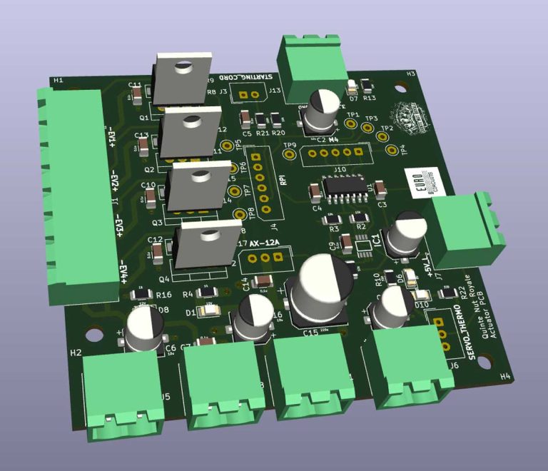
The Actuator Board is the powerhouse of our robot. It serves as the critical interface between our logic controllers (an Adafruit Metro Grand Central M4 and a Raspberry Pi 4) and the high-current physical actuators.
Power Management and EMI Isolation
Because this board handles both noisy power electronics and sensitive logic signals, isolation was our top priority. We implemented multiple voltage domains: 12V for the vacuum pump and solenoid valves, 10V for the Dynamixel servos, and 5V/3.3V for the logic ICs.
To combat EMI, we utilized the bottom layer of our Eurocircuits PCB to create two distinct, uninterrupted ground planes (Logic GND and Power GND). Eurocircuits’ highprecision manufacturing allowed us to perfectly route our traces without ever crossing and breaking these ground planes. Furthermore, we integrated 10μF reservoir capacitors for transient spikes, 0.1μF decoupling capacitors near ICs, and auto-resetting polyfuses to protect against overcurrent conditions like a stalled motor.
Pneumatic Solenoid Interface
Our vacuum gripping system requires rapid, reliable actuation. We designed a Low-Side switching circuit driven by IRLZ44N MOSFETs. When the Raspberry Pi sends a 3.3V high signal, the MOSFET saturates, sinking the 12V solenoid to ground. To protect the transistors from the inductive kickback when the valves close, we included anti-parallel flyback diodes.
Dynamixel Half-Duplex Conversion
Our grabbing mechanism uses four heavy-duty Dynamixel AX-12A servo. Dynamixels use a single-wire Half-Duplex UART protocol, whereas our microcontroller uses standard Full-Duplex (separate TX/RX). We engineered an elegant hardware solution using a 74LVC2G241 dual buffer with a 3-state output to automatically toggle between transmission and reception based on a Transmit Enable (TXE) pin, complete with pull-up resistors to keep the bus stable.
Strict Routing Standards
Given that the four Dynamixels can draw transient peaks up to 6A, and our vacuum pump draws a continuous 1.5A, standard trace widths would melt. Adhering to the IPC-2221 standard, we calculated a required trace width of 1.85mm for the servo bus and 1.3mm for the pump rail (allowing a safe ΔT = 10◦C). Eurocircuits handled these massive power traces alongside the delicate 0.4mm logic traces with zero etching flaws.
Deep Dive: The Sensor Board
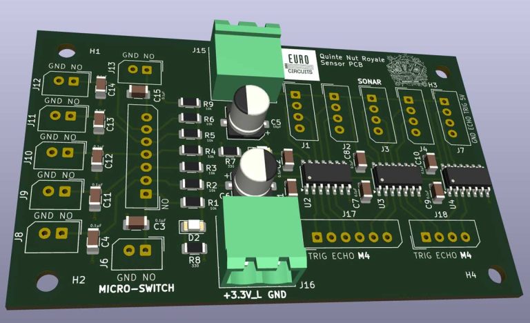
If the Actuator board is the muscle, the Sensor Board is the nervous system. This second PCB centralizes all inputs from our spatial awareness sensors.
Level Shifting and Logic Safety
The Adafruit M4 logic runs natively at 3.3V, but our HC-SR04 ultrasonic sonars operate at 5V. To prevent the 5V echo signals from frying our microcontroller, the Sensor Board incorporates TXS0104E bidirectional level shifters. This guarantees safe, highspeed 3.3V ↔ 5V conversion.
Hardware Debouncing
We rely on 7 micro-switches to detect when a “nut” block is successfully gripped. Mechanical switches inherently “bounce” (rapidly open and close) when pressed. To prevent our software from reading multiple false triggers, the Sensor Board includes hardware RC decoupling and pull-up networks for every switch line, delivering a perfectly clean digital edge to the M4.
We kept trace widths at a standard 0.4mm for this board since current draw is negligible (max 75mA for all sonars combined). The build quality from Eurocircuits ensures that these delicate sensor signals reach the processor without any parasitic resistance or signal degradation.
See It in Action!
We are incredibly grateful to Eurocircuits for their support. The professional quality of these PCBs has given us a massive competitive edge by eliminating electrical gremlins and allowing us to focus entirely on software and strategy.
Want to see our custom electronics in action? Check out our project video here: https://youtu.be/Xgs_F0qRc_k.
We are incredibly proud of our 10th place finish at the Eurobot International Finals. Thanks to Eurocircuits!

For more information visit the UC Louvain website.
Bring your product to market on time and within budget – join the Eurocircuits Community


