TU Delft Hydro Motion Team: Hydrogen-Powered Hydrofoiling Innovation
The TU Delft Hydro Motion Team is a student engineering team aiming to inspire the maritime industry to adopt sustainable technologies. How do we do this? Every year, we build a hydrofoiling boat powered by sustainable energy to compete in the Monaco Energy Boat Challenge. For the first 15 years of this team’s existence, we powered the boat with solar energy. After having won the competition on solar energy, we switched to using a hydrogen fuel cell. In 2026, we strive to be the first team in the competition to race on liquid hydrogen, which is three times as energy dense as gaseous hydrogen, allowing us to store the same amount of energy in a smaller space.
About The Boat
A hydrofoiling boat powered by a hydrogen fuel cell requires a lot of control systems. Not only the fuel cell requires control, but the tanks, the buffer, the motor, and the height actuation motors need to be controlled as well. All of this control is done by software that we write ourselves, which runs on PCBs that we design ourselves, and are manufactured by Eurocircuits. But not all PCBs do control. Some are more accurately classified as power components, which do control on the side…
The Buffer PCB
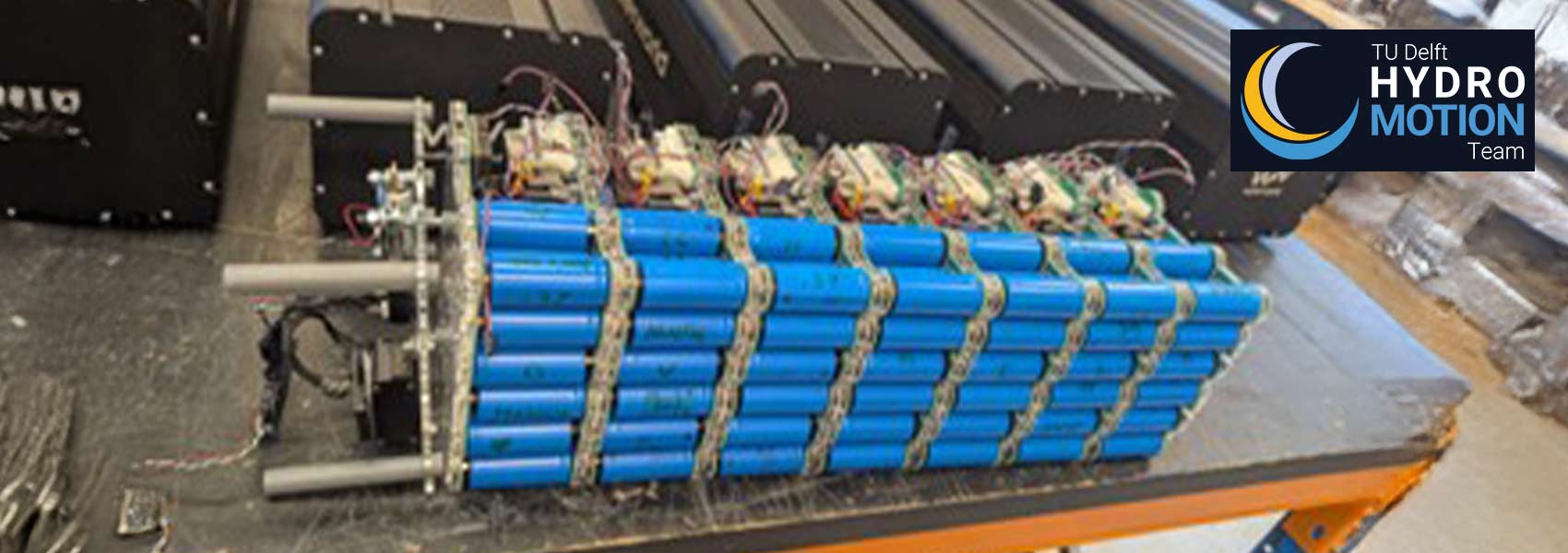
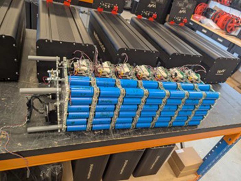
The buffer is a powerful battery that acts as, well, a buffer. The fuel cell being a fluid dynamics component, it can not respond to changes in electrical power demand sufficiently quickly. Such changes frequently come from the motor during acceleration and deceleration. The buffer picks up the temporary slack, giving the fuel cell time to match the demand. We are very proud to say that we make this buffer ourselves and a very crucial part of the buffer is the buffer PCB, which acts as the connection point for the battery cells, ensuring that the circuit topology is correct. Another nice thing about the buffer PCB is that it provides a convenient connection point for the Battery Management System and gives it electrical access to the power circuit. The buffer consists of seven layers of cells stacked on top of each other and between each layer is a buffer PCB.
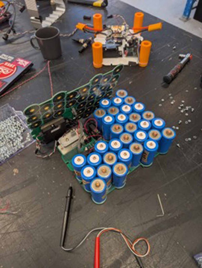
Making The Buffer
We started out by making some design changes to the buffer of the previous year. Mainly, to prevent overheating, we incorporated internal ventilation fans. These design changes impacted the buffer PCB design, which was updated accordingly. After submitting the design to Eurocircuits, we received technical feedback about design for manufacturability from an engineer at Eurocircuits, which we used to update the design further. For our first order, we ordered two PCBs, which we used to make a single cell layer, sandwiched between the PCBs. We used this layer to test the electrical and thermal characteristics of the batteries. With confidence that the layers were sound, we ordered the rest of the buffer PCBs (the buffer has 18 in total) to make the entire buffer.
For more information please visit the Hydro Motion Team website.
Bring your product to market on time and within budget – join the Eurocircuits Community


![]()

