User Guides
Our User Guides provide step-by-step instructions on how to use our free online smart tools and other available software.
Written by Claudia Mallok. 17/03/2026
In many industrial products, the mechanical framework is defined before electronic design begins. Housing geometry, mounting points and physical constraints determine how the PCB must be positioned within a limited installation space.
The challenge therefore extends beyond electrical routing to include geometric integration, particularly as increasingly compact products demand a three‑dimensional PCB configuration within a predefined housing.
Designers evaluate various architectural options: multiple rigid PCBs connected by cables or board‑to‑board connectors, flexible or rigid‑flex constructions, or a multilayer design incorporating a flex‑to‑install capability.
If the assembled product is not intended to be separated and bending is required solely to achieve the final installation geometry, integrating the bend function directly into the PCB structure provides a simple and controlled method of realising 3D PCB integration.
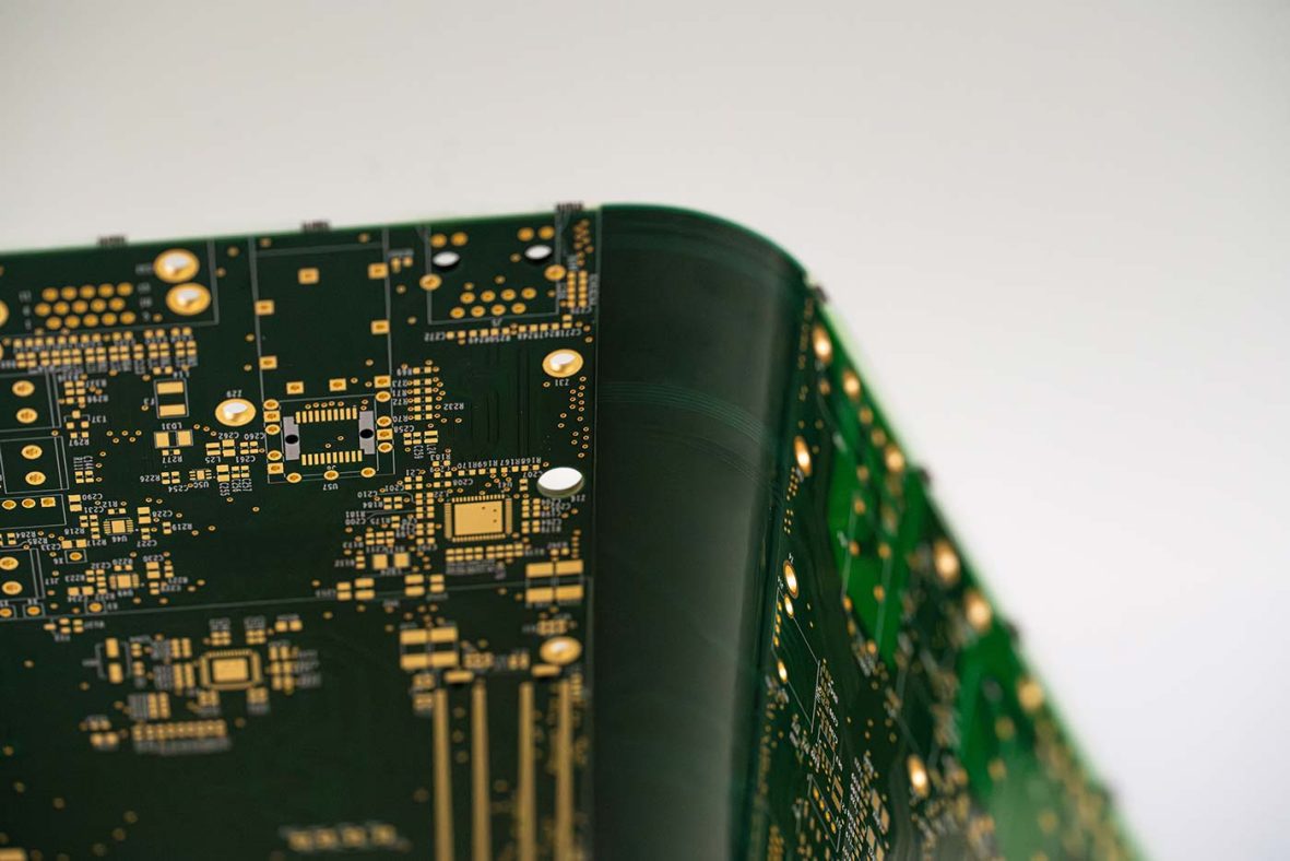
SEMI‑FLEX achieves this through structured FR‑4 multilayers incorporating a dedicated bend zone, providing a reliable and controlled flex‑to‑install capability. By reducing interconnect transitions, connectors, and mechanical assembly elements, the concept lowers architectural complexity and enhances overall system cost efficiency, while remaining within clearly specified mechanical limits.
Using this approach, the bending capability is integrated within the multilayer PCB structure itself eliminating the need for discrete flex circuits or additional interconnect solutions.
SEMI-FLEX integrates a defined bend zone into a standard FR-4 multilayer PCB. The bending is performed during installation to achieve the required 3D geometry. Once in place, the PCB remains mechanically stable throughout operation.
Within defined limits, the PCB functions not only as an electrical interconnect carrier but also as a structural element of the installation geometry.
Unlike constructions intended for repeated dynamic flexing, SEMI‑FLEX is engineered specifically for controlled bending during installation. It introduces no additional material systems, such as polyimide layers, and instead remains fully within established FR‑4 manufacturing processes.
Using standard FR-4 materials avoids the additional cost associated with specialised flex materials when dynamic performance is not required.
SEMI‑FLEX enables the consolidation of multiple interconnected assemblies into a single multilayer PCB with an integrated bend zone.
This can reduce:
Fewer interfaces generally result in a structurally simpler architecture with fewer mechanically and electrically stressed transition points.
Crucially, simplification is achieved through structural integration of the bend zone, not by reducing defined mechanical safety margins. Operational reliability remains governed by specified bend radii and mechanical limits.
The overall performance of SEMI-FLEX is determined by how the bend zone is engineered within the multilayer buildup.
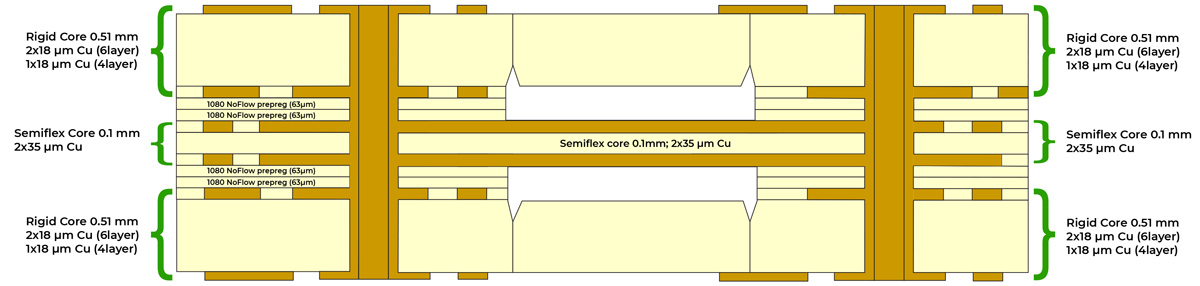
Eurocircuits employs a specialised core‑build process for manufacturing 4‑ and 6‑layer SEMI‑FLEX designs.
The bend zone is defined by:
The multilayer build is manufactured symmetrically using:
This results in a structurally symmetrical multilayer construction.
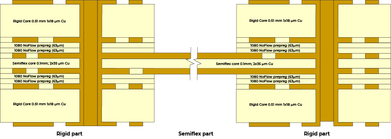
Structural symmetry ensures uniform material distribution across the bending axis. It defines a stable mechanical neutral axis and enables controlled bidirectional bending (up to ±180°).
An alternative method is to manufacture a standard multilayer PCB and create the flex area by depth-milling material after lamination. While technically feasible, depth-milling requires precise process control. Variations in milling depth may lead to uneven flex thickness and less consistent bending behaviour.
In contrast, the Eurocircuits core-build solution defines the bend zone structurally rather than through post-processing material removal. Although it involves additional manufacturing steps, it establishes the mechanical characteristics of the bend area within the buildup itself.
The result is:
The predefined SEMI-FLEX pool buildups establish clearly specified mechanical boundary conditions:
The required bend zone length can be estimated using:
L = (2 × π × bend radius) × (bend angle / 360)
For example, five bends of 180° at a radius of 5 mm require a minimum bend zone length of 15.7 mm. These limits assume balanced copper distribution within the bend region.
Exceeding the specified mechanical limits may result in copper fatigue or localised stress concentration. The defined envelope should therefore be treated as a structural design constraint, not as a flexible recommendation.
SEMI-FLEX delivers the greatest benefit when considered early in system architecture and mechanical layout planning. For detailed specifications and design guidelines see SEMI-FLEX pool page.
The Eurocircuits SEMI-FLEX pool is not a generic flex offering, but a defined industrial implementation based on validated 4- and 6-layer FR-4 buildups with specified mechanical and electrical parameters.
By limiting the design space to predefined constructions, the pool ensures controlled bending behaviour, reproducible mechanical characteristics, and predictable manufacturing performance.
Unlike fully custom constructions, where mechanical behaviour depends on individually defined buildups and process variations, the SEMI-FLEX pool provides a validated framework with known performance characteristics. This reduces development uncertainty and shortens the path from layout to functional PCB.
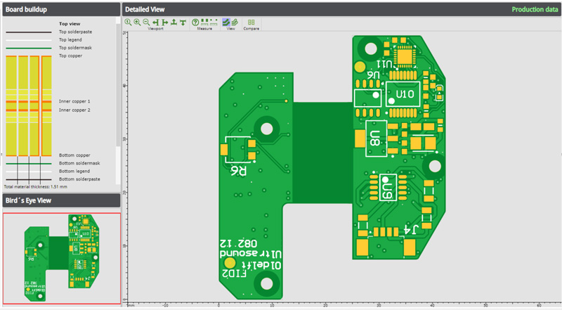
The buildups are fully integrated into the Eurocircuits Visualizer environment. Designers can upload layout data, select the SEMI-FLEX construction, and verify manufacturability as well as compliance with defined bend zone constraints during development.
Instant online pricing enables simultaneous evaluation of geometry, feasibility, and cost implications at layout stage reducing uncertainty before release.
Pooling therefore supports predictable prototyping and small-series production within a clearly defined mechanical framework.
Designers can extend this approach to fully assembled prototypes. Within the same digital environment, layout data, BOM, and component placement files are validated prior to order release. This enables virtual manufacturability verification of the complete PCB assembly, including design rule checks, component availability, and sourcing consistency.
By combining defined SEMI-FLEX buildups with integrated PCB manufacturing and assembly, developers can align mechanical feasibility, electrical functionality, and manufacturability before physical production begins. This reduces redesign loops and increases the likelihood of achieving functional, installation-ready PCBs at the first build stage.
SEMI-FLEX is a defined mechanical integration concept based on standard FR-4 multilayer technology.
It enables compact 3D installation geometry by incorporating a structurally defined bend zone directly into the multilayer build. The bending behaviour is specified and controlled within defined mechanical limits and intended for installation-related forming rather than repeated flexing.
By embedding the bend zone into the PCB architecture, SEMI-FLEX can consolidate assemblies, reduce interconnect complexity, and simplify mechanical integration without introducing additional material systems.
Within a validated and standardised implementation framework, the concept supports predictable prototyping and industrialisation using established FR-4 manufacturing processes.
SEMI-FLEX is therefore not a substitute for dynamic flex technology, but a cost-conscious solution for installation-driven 3D PCB forming in compact mechanical environments.