
PCB markings: custom markings for your PCB
PCB markings: custom markings for your PCB
A PCB design contains many details that influence manufacturing success: layer structure, routing, component placement and design rules. Before production starts, there are also smaller details to review. One of them is the information printed on the PCB.
Logos, QR codes, order numbers, production information or UL markings may be required for identification, traceability or certification. Their position needs to fit on the finished PCB: visible where needed, away from critical areas and suitable for manufacturing.
The Eurocircuits PCB Visualizer is the interface between the PCB designer and the manufacturing process. It allows designers to upload their PCB data, review manufacturing-related information and make adjustments where required.
The Marking Editor is one of the tools within this environment. It allows designers to define and position additional PCB markings directly using the GUI of the PCB Visualizer.
PCB design data and additional markings
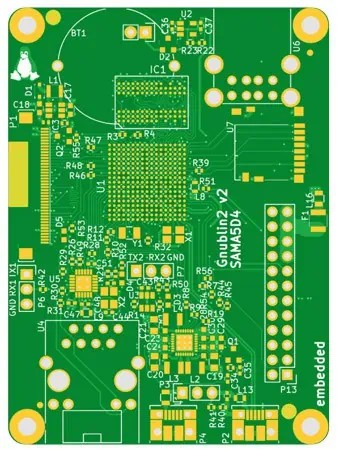
PCB designers define many elements that appear on the finished PCB directly in their PCB design software. These can include:
- component reference designators
- polarity indicators
- pin-1 markers
- logos or other graphics that are part of the PCB layout
These elements are included in the PCB design data and transferred together with the manufacturing files.
In addition, some projects require further markings for identification, traceability or certification purposes. These markings can include:
- order numbers
- production-related information
- QR codes
- UL markings
- customer-specific markings
The Marking Editor is designed to manage these additional markings within the PCB Visualizer workflow. It allows designers to define their position, adjust their orientation and check their placement without changing the original PCB layout.
For information about designing readable and manufacturing-friendly legend information, see: Best Practices for Legend Print
Why marking placement matters
A marking may look correct on the screen but still may create problems if its position is not considered carefully.
A few practical rules help avoid issues:
Keep markings away from critical areas
Avoid placing markings on:
- solder pads
- holes
- cut-outs
- exposed copper areas
This helps maintain reliable assembly conditions and keeps the information readable.
Consider the assembled PCB
A marking underneath a component is usually no longer useful. Important identification or service information should remain visible after assembly.
Use readable dimensions
Very small text or graphics can become difficult to read after production. Eurocircuits recommends: minimum text height: 1 mm, minimum line width: 0.1 mm
Use the right data for assembly information
The PCB legend supports identification and service. Assembly instructions should be provided through dedicated manufacturing data such as CPL files and assembly documentation.
The Marking Editor: part of the PCB Visualizer workflow
The Marking Editor is part of the Eurocircuits PCB Visualizer Toolbox. This provides designers with an interactive environment to communicate with the Eurocircuits manufacturing process. It combines design data analysis, manufacturing checks and editing functions in one workflow.
The Marking Editor adds another option: designers can define and adjust additional markings directly on the PCB view. By combining visualisation, design checks and manufacturing-related information, it creates a digital view of the PCB before production starts.
The Marking Editor adds another option: adjusting additional markings directly in the PCB view. Instead of describing marking positions separately, designers can define the position directly in PCB Visualizer and immediately see how the marking fits into the PCB layout.
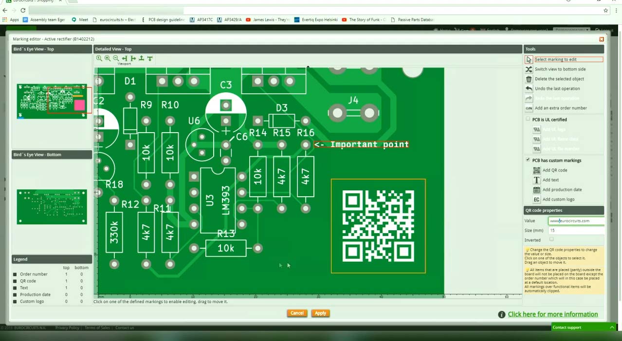
With the Marking Editor, you can:
- add custom text, QR codes, logos, order numbers, production dates and UL markings
- place markings on the top or bottom side of the PCB
- move and rotate markings directly on the screen
- import logos in JPEG, PNG, GIF or BMP format
The changes can be reviewed directly in PCB Visualizer before saving the final settings. The PCB Visualizer and its tools are available free of charge for Eurocircuits users.
How to use the Marking Editor
Adding and adjusting markings is straightforward:
- Load your PCB job into PCB Visualizer
- Open the PCB Configurator
- Select UL marking or Specific marking under Advanced options
- Click the Marking box to open the Marking Editor
- Add, move and adjust your markings
- Click Apply and save your changes
The marking legend shows which markings are placed on the top and bottom side of the PCB. For a detailed explanation of all functions and a step-by-step guide, see the: Marking Editor User Guide
Small details matter
Additional markings are only a small part of a PCB design, but they become part of the finished board. Defining their position clearly during PCB preparation helps avoid unclear information, hidden markings or unnecessary corrections later in the process. The Marking Editor provides a simple way to define and adjust these markings directly in PCB Visualizer.
Bring your product to market on time and within budget – join the Eurocircuits Community


