User Guides
Our User Guides provide step-by-step instructions on how to use our free online smart tools and other available software.
Eurocircuits generates a PCB Passport for every PCB delivered whether it is a bare board or bare board with assembly order.
The PCB Passport is confirmation that the delivered PCB(s) conforms to the order parameters and relevant manufacturing tolerances.
Our customers can with confidence then use the PCB Passport to give to their customers as part of the specification for the product they supplied.
The PCB Passport is available to download once the order has been shipped. To find and download the PCB Passport first Sign in to your Eurocircuits Customer Account.
From the CALCULATE AND ORDER menu of the left-hand side select either, View running orders or Order repeats/view history.
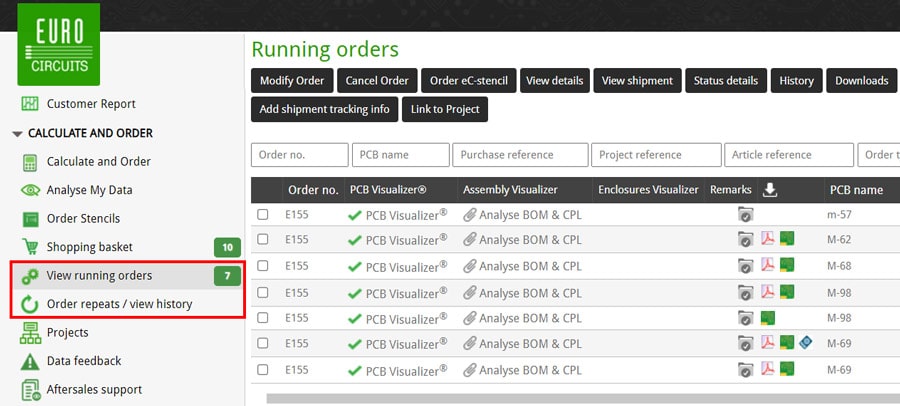
To download the PCB passport for a specific order, you can either click on the PCB Passport icon ![]() in the Download column.
in the Download column.
![]()
The PCB passport will be downloaded to your computer and can be found in your designated download folder on your computer.
Alternatively, check the box at the start of the row of the appropriate order and click on the Downloads button at the top.
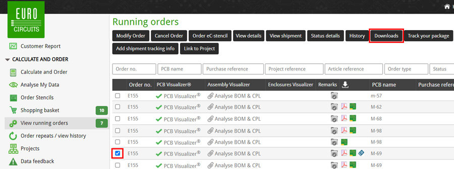
This will open a popup window.
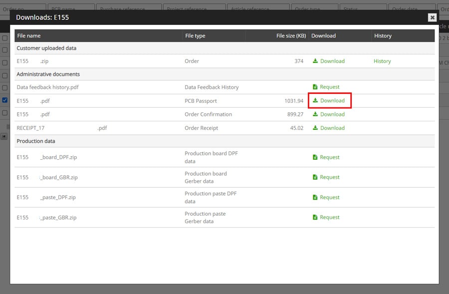
Next click on Download in the row containing the PCB passport.
The PCB passport will be downloaded to your computer and can be found in your designated download folder on your computer.
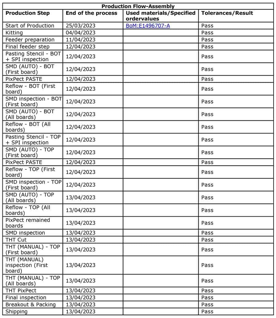
The passport is split into several sections that provide various information on the manufacturing and assembly process.

This section details the relevant Eurocircuits handling company information and the Eurocircuits internal Order Number.
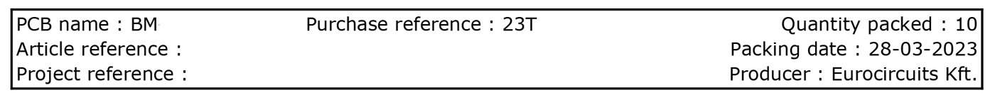
This section contains the following information when available:
This section shows graphical images of the Top and Bottom of the bare board PCB in the delivery format as defined in the order.
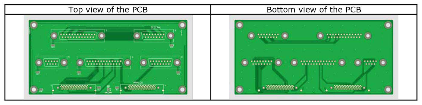
Example of Single PCB Delivery Format
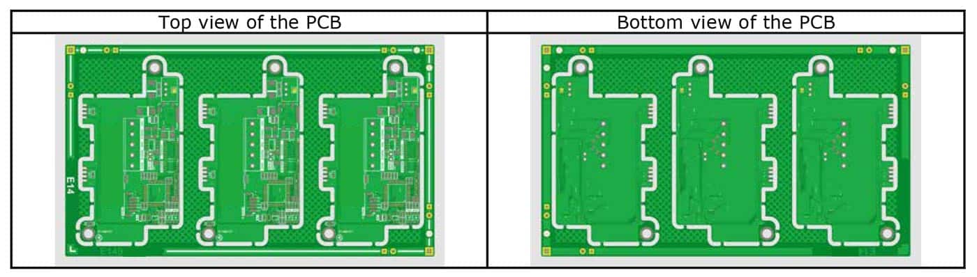
Example of PCBs in Panel Delivery Format
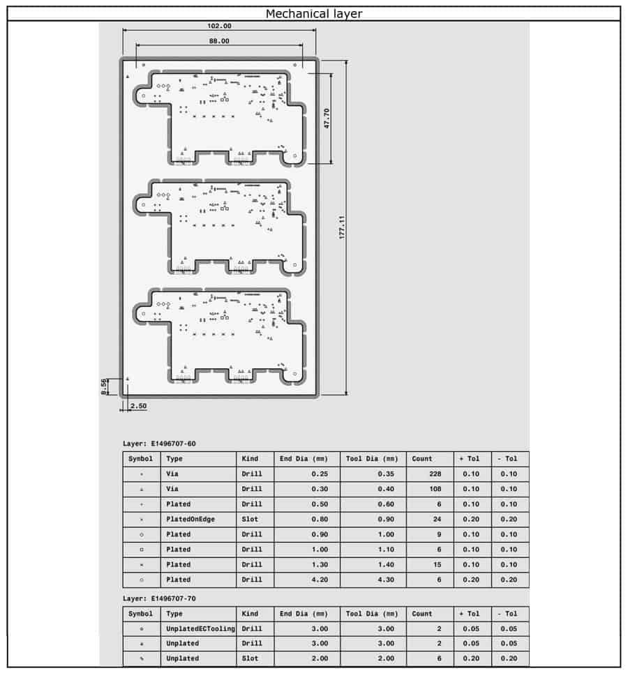
This section has two parts, the first is a graphic of the PCB or panel with PCBs with the location of the drilled holes and slots identified by a unique symbol for each hole or slot size.
It also has the X & Y dimensions of the PCB and the panel (if the delivery format is the panel) and the X & Y dimensions to the reference point on the PCB or panel.
The second part contains two tables, the first with details of the plated holes and slots and the second with details of the unplated holes and slots.
Each row of the table contains information about one specific hole or slot size. The first column of each row contains a unique symbol which can be cross referenced to the symbols on the image above.
The columns of the tables contain the following information:
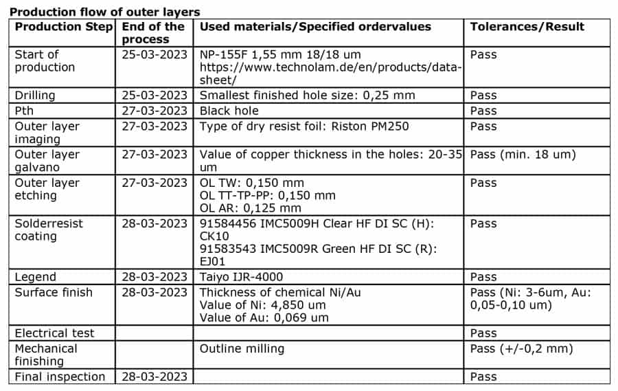
This section contains a table that shows the following information for appropriate parameters:
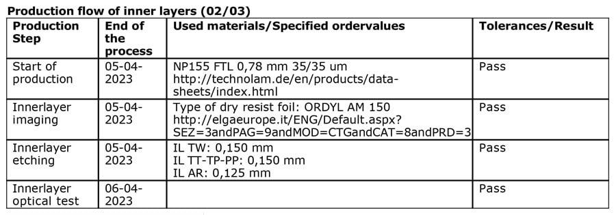
This section contains a table that shows the following information for appropriate parameters:
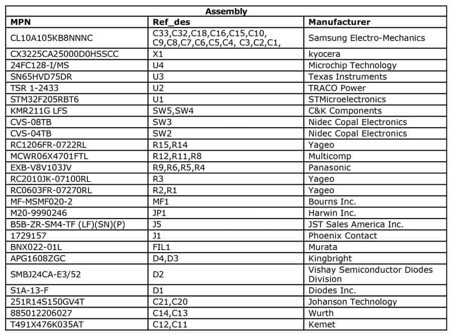
This section contains a table that details the BOM information used to assemble the PCB(s).
Each row of the table contains the following information for each component type used:
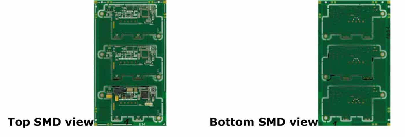
This section shows graphical images of the Top and Bottom of the assembled PCB in the delivery format as defined in the order.
This section contains a table that shows the following information for appropriate parameters: