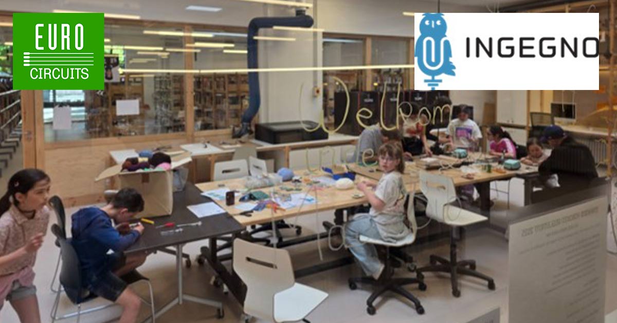
Bring your product to market on time and within budget – join the Eurocircuits Community
Formula Student Team Delft Blog Banner

Efficient High Voltage Motor Power

As Formula Student Team Delft we have been building formula-style race cars for 20 years now, of which the cars of the last 10 years have been electrically propelled.

What started out as an electrical system with exclusively OEM (original equipment manufacturer) parts, is now an almost fully self developed system in our latest car; the DUT19. Self-developing PCBs gives us full design freedom, which leads to better performance and a more tailored end product.

Systems such as a battery management system (both high- and low voltage), a dashboard, an ECU and various safety systems were already self-developed in the DUT19.

The final piece of the puzzle is to include our own high voltage motor controllers to that list. In this post I touch on how the motor controllers (MCs) work, how our design looks and what our plans for the future are.

Motor Control Basics

Basically, the powertrain of any electric vehicle consists of three parts: a battery, a motor controller (also called inverter) and a motor.

In our car, we make use of permanent magnet synchronous motors (PMSM). These motors need alternating current (AC) to run.

A battery is, however, a direct current (DC) source. We use a motor controller between the battery and the motor to invert the DC from the battery into AC for the motor.

With the motor controller we can also regulate the speed and torque that is put on the motor.

We have not used a self-designed motor controller in any of our cars yet because it is quite a bit more difficult to get proper performance and reliability out of than other electric systems that we did already design ourselves.

Because it was not possible for us to do a full design, build, test and integration- cycle in one year like we normally do, we started a committee and worked on the project for multiple years.

Our goals for the final system are saving weight, improving efficiency, decreasing package size and increase controllability.

specially that last aspect can be very interesting, since we would be able to run our control software, such as traction control, at higher frequencies. This will make us go faster on track in the end!


MC_stack1

Picture of the motor controller stack: LV, isolation and HV

Our PCB Design

The latest iteration of the MC system is build up out of three individual PCBs; a low voltage PCB, an isolation PCB and a high voltage PCB (top to bottom on the pictures).

The HV board performs the actual inverter function: it has the battery connected on one side and the motor on the other side. It houses a few big transistors that can switch the battery voltage onto different motor connections very quickly, this is the essence of inverting.

The LV board takes input from the rest of the car such as encoder data (current motor speed) and speed/torque targets. It then uses this data in the motor control software loop and tells the transistors on the HV board what to do.

The isolation board is the interface to ensure safe isolation between the low- and high voltage systems.

The LV board is the brain of the MC package. It includes a control card on which we can load our control software that we build in MATLAB and Simulink.

The software is basically a feedback loop that regulates the motor from the current motor speed to the new speed target. The LV board also performs the safety features of the system.

Among other things, it measures the output current to the motor with the three blue current sensors. Making use of these sensors, together with some analogue circuitry we protect against instantaneous peak over-currents, as well as RMS over-currents.

As said before, the HV board houses the transistors. In our case, this is a single package 6-pack of Silicon Carbide field-effect transistors (better known as SiC-FETs).

Silicon Carbide is a relatively new transistor technology, mostly praised for its small footprint, light weight and high efficiency. The package is mounted on the bottom side of the PCB, so we can push it onto a cooling plate to dissipate the conversion losses. The HV board also contains a bunch of capacitors on the DC (battery) side of the board for filtering.

Finally, for the interface between LV and HV, we use the isolation PCB.

For the safety of our driver and all people involved, the HV system needs to be properly isolated from everything else. For this reason, we cannot simply directly connect the signals from our LV control card to the HV SiC-FET.

The isolation board has little LV sections to which the LV board is connected. It then uses isolated power supplies and gate drivers to make the signals from the LV board into isolated signals that can be pushed to the HV board from little HV sections on the same isolation PCB.

For safety, there is a minimum distance between the HV- and LV sections. Next to that, we also use conformal coating on the board to improve isolation.


MC_stack2

Picture of the motor controller stack mounted on a cooling plate with the motor wires connected

Testing

We can connect to the LV board with USB for easy programming. We can also connect to it with CAN, a widely used communication protocol in the automotive industry.

he latter is also used in the car. We have our own dyno test setup. Here, we can mount two motors towards each other with a torque/speed sensor in between. These motors spin up to 20,000 (!) rpm, so the alignment needs to be perfect to avoid big vibrations.

In the first tests, we use only one motor and let it spin freely, without any load. In this way, we can test the full speed scale without using much power, as there is almost no torque when free spinning.

You can already test a decent part of the system this way; part of the control loop, integration with the encoder (motor speed sensor) and some safety features.

Later, we moved to the setup shown in the picture, using a counter motor. In this setup, one motor is connected to our own motor controller, and the other to an OEM motor controller.

We can simulate the torque of actually driving on the road by letting our counter motor exert force in the direction opposite to our main motor.

With this setup, we can test the full scale of speed and torque of the motor and thereby also the full power range of our motor controller.

With the torque/speed sensor in the middle, we can perform efficiency calculations. Since we know our voltage and current input (electrical power) as well as the torque and speed on the output (mechanical power), we can find the efficiency of the total system at different loads.

We were actually able to test a real load cycle with this setup, by running speed and torque data that we acquired from driving with our older cars during competitions.

In a race we do not only use the motors to propel the car forwards, but also to electrically brake. By using the motor as a generator and reversing the conversion of the motor controller, we turn the AC power back into DC to charge the battery. During testing, we feed this power back to the net (or our counter motor).

While we are pretty content with the initial results on efficiency, we also ran into some challenges, one of the biggest ones being cable reflections. Cable reflections are pretty complex to predict but in general; higher change in voltage (faster transistor switching) and longer length cables result in higher voltage reflections.

Reflections can become an issue if standing waves occur and the voltages of waves add up, surpassing the voltage rating of for example the motor.

This can cause the isolation of the windings of the motor to break and therefore the motor.

For now we mitigated this by increasing the rise- and fall time of our transistors, reducing the rate of change in voltage. This however comes at the loss of efficiency.

We are looking into a solution that doesn’t decrease our performance.

Since we use four motors in the car, we will also make use of four motor controllers. We have yet to test with multiple of our own motor controllers packaged close to each other.

This is also important to test since the electro-magnetic interference (EMI) that the SiC-FETs generate might influence the performance of other electronic systems close to it. In conclusion, there is still more than enough testing to be done!


A picture of our test setup: the two motors connected through a torque/speed sensor

A big thank you to Eurocircuits for making this adventure possible for us!

Mathijs van Geerenstein (Chief Electrics DUT20)

https://www.fsteamdelft.nl/

Be the first to read all about our news and information. Follow us on

linkedin-logo fb-logo Twitter_Icon youtube-logo-full-color ec-tv-black