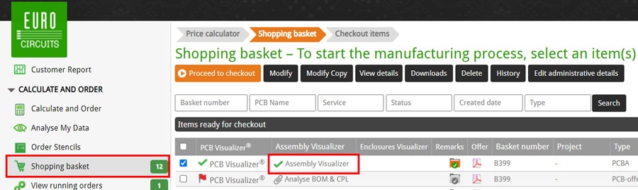
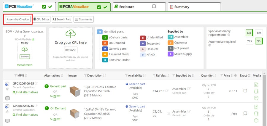
The Assembly Checker
There are 3 sections in the Assembly Checker window:
- Issues – This is a table format listing the issues found.
- Fault view – This displays the current selected issues graphically with a text description.
- Detailed view – This shows PCB (graphically) with the current selected issues highlighted.
Additional parameters are:
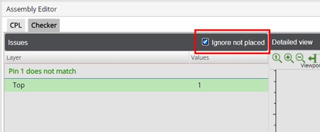
- Ignore not placed Check Box – If you check this box all parts designated as Not placed or Customer in the Supplied by column of the BOM Editor will not be shown.
IMPORTANT
- We recommend using the Assembly checker to review all components placement on the PCB even if they are not being placed by Eurocircuits.
- To save any changes please click on the orange Apply button at the bottom of the Assembly Editor window.
Issues Section
This section displays the type of issues found such as:
- Pin 1 does not match.
- Components close to or outside PCB outline.
- Footprints do not match.
- Incorrect component rotation.
- Etc….
Below each issue, it identifies the associated layer (Layer) and the number of times (Values) the issue occurs.

Example – Multiple Issues
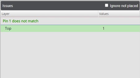
Example – Single Issue
If you click on any of the issues it will place the issue in the centre of the Detail view section and display the first occurrence of the issue in the Fault view section.

Fault view Section
The Fault view will provide details of the issue selected in the Issues section; it also shows the number of occurrences of that specific issue.
The issue selected is displayed in the Current issue box and you can move to the next occurrence of that issue by clicking the arrows (left or right).
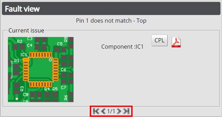
Current issue box
In this box the issue selected will be displayed graphically and at the same time the issue will be centralised in the Detailed view section, the component designator will also be displayed.

Alongside the component designator there is the CPL button, this will open the CPL Editor
displaying the component and the current information available.
In addition, if information is available for the part the PDF icon  will be displayed (next to the CPL button), click on it to access the information available (this may open a file from another website).
Detail view Section
This allows you to view the PCB (graphically) and review the issues found, as you scroll through the issues in the Fault view each occurrence will be highlighted and displayed in the centre of the Detailed view.

At the top left of the Detailed view section are the available tools:
- View port
- Measure
- Board view
- Output

Viewport

The following functions are available in the Viewport, simply click on the required icon to activate the function.
 Total view – Display all data in the board outline.
 Zoom in – with a factor x2. The image centre point is unchanged.
 Zoom out – with a factor x. The image centre point is unchanged.
 Pan left – Moves the viewport to the left, which moves the image to the right.
 Pan right – Moves the viewport to the right, which moves the image to the left.
 Pan up – Moves the viewport up, which moves the image down.
 Pan down – Moves the viewport down, which moves the image up.
In addition, these functions can also be performed by using the mouse:
- Click with the left mouse button to zoom in.
- Click with the right mouse button to zoom out.
- Press a mouse button and drag to pan.
- Use the mouse wheel to zoom in and out.
Measure
The following functions are available in the Viewport, simply click on the required icon to activate/deactivate the function.

 Object info
When activated information is displayed about the object at the mouse location in the top left corner.
The information contains the shape and position info along with the layer on which the object is found.
If there are multiple objects available at the same location, click the right mouse button to display the information on the next object in the stack. Objects from all selected layers can be queried.
To deactivate this function, press the ESC key, click the button again or select another function.
 Measure object clearances
If this function is active, you can select 2 different objects and measure the clearance between both.
Move the mouse over the first object and click to lock the first object. In case multiple objects overlap, you can click the right mouse button to highlight the next object in the stack before selecting it.
Then move the mouse over the second object. Information about both objects is displayed together with the clearance between both objects.
To deactivate this function, press the ESC key, click the button again or select another function.
 Measure point distance
If this function is active, you can select 2 different points and measure the clearance between them.
Move the mouse to the location of the first point, an orange cross cursor will snap to special points in the data set, e.g., centre points of flashes or start and end points of lines.
To override the snapping functionality, hold the Shift key pressed. Click to lock the first point.
Then move the mouse to define a second point. The coordinates of both points are displayed together with the distance between both points. Using this method, it is possible to measure e.g., the pitch of a component.
To deactivate this function, press the ESC key, click the button again or select another function.
Board view

These buttons reset the zoom of the Detailed view to display the full PCB.
Output

To output the current image in the Detailed view click on the preferred format.