Using the Compare Function
The compare function works in a similar way in all 3 PCB Visualizer tools.
When the selected layer is displayed it will show different colours where appropriate.
- GREEN – what was added.
- RED – what was removed.
- GREY – no change.
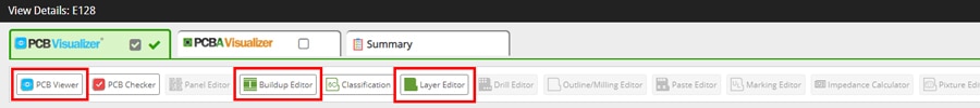
PCB Viewer
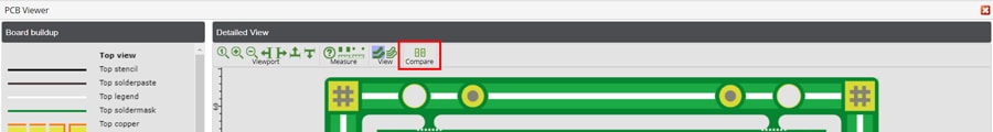
Click on the Compare icon  at the top of the Detailed View section.
Next select the layer you wish to compare by clicking on the layer name (layer type) in the Board buildup section.
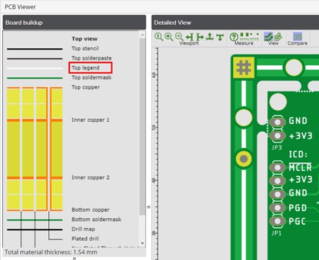
This will display the layer in the Detailed View section.
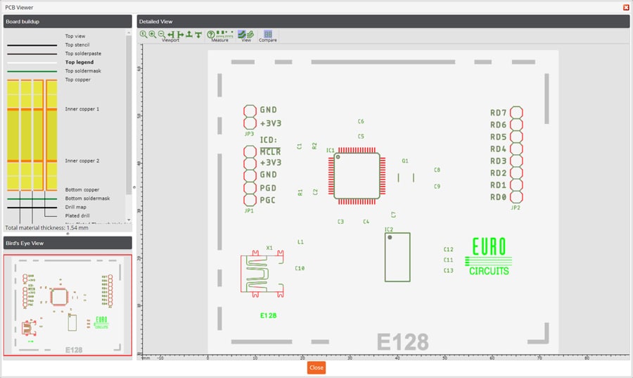
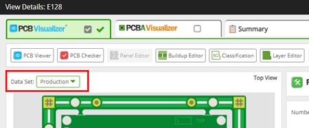
You can now review the differences between the original data that you uploaded and the production data (SI) based on the colours displayed.
Clicking on the Compare Function icon allows you to switch between the compare data and the production (SI) only data.
To compare another layer simply click on the layer in the Board buildup section.
Buildup Editor
Click on the Compare icon at the top of the Detailed View section.
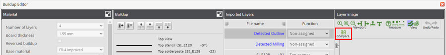
Next select the layer you wish to compare by clicking on the layer name (layer type) in the Board buildup section or on the File name in the Imported Layers section.

This will display the layer in the Layer Image section.

You can now review the differences between the original data that you uploaded and the production data (SI) based on the colours displayed.
Clicking on the Compare Function icon allows you to switch between the compare data and the production (SI) only data.
To compare another layer simply click on the layer in the Buildup section or the Imported Layers section.
Layer Editor
The Layer Editor is similar to the Buildup Editor, the difference is that in the Layer Editor the Buildup section is collapsed (not visible).
First, click on the Compare icon at the top of the Detailed View section.
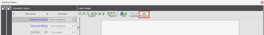
Next select the layer you wish to compare by clicking on the File name in the Imported Layers section.

This will display the layer in the Layer Image section.

You can now review the differences between the original data that you uploaded and the production data (SI) based on the colours displayed.
Clicking on the Compare Function icon allows you to switch between the compare data and the production (SI) only data.
To compare another layer simply click on the appropriate File name in the Imported Layers section.